Isuzu KB P190. Manual — part 64
3A-8 FRONT ALIGNMENT
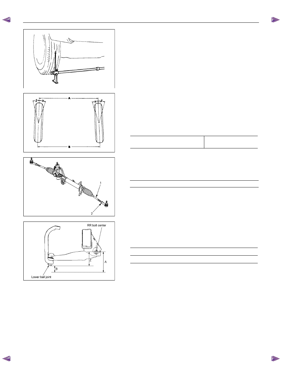
Toe-in Adjustment
Measurement should be taken with the vehicle on a surface
plate.
If a surface plate is not available, toe-in should be checked
with the vehicle parked on a level floor.
1. Set front wheels to straight ahead position.
2. Align the toe-in gauge with center height of each wheel at
front end.
3. Apply center marks to each wheel, then take measurement
of distance A between the center marks on each wheel.
4. Slowly move the vehicle rearward until the center marks
reach the rear end position.
5. Take measurement of distance B between the center
marks at rear end.
The toe-in can be calculated with the following formula.
Toe-in = B - A
Toe-in mm
(in)
4
×2
(Except high ride suspension)
0
±2 (0±0.08)
To adjust the toe-in angle, loosen the lock nuts (2) on the tie
rod (1) and turn the tie rod. Turn both rods the same amount,
to keep the steering wheel centered.
Lock Nut Torque
N
⋅m (kgf⋅m/lb⋅ft)
98
±6.0 (10.0±0.6 / 72.3±4.3)
RTW53ASH000101
Trim Height
Trim Height : at Curb Weight (Reference Data)
Trim height (Z) = A - B
Front mm
(in)
Z
105(4.13)
FRONT ALIGNMENT 3A-9
RTW53ASH000201
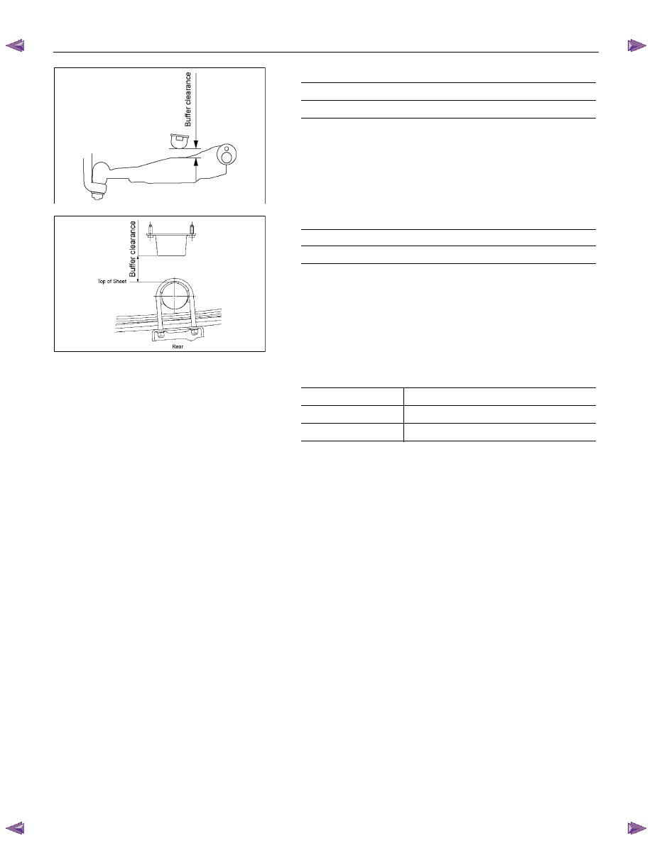
FRT Buffer clearance (Reference Data)
mm(in)
4
×2 (Except high ride suspension)
25.9(1.02)
RTW340SH000101-X
RR Buffer clearance (Reference Data)
mm(in)
4
×2 (Except high ride suspension)
82 (3.23)
MAXIMUM STEERING ANGLE
4
×2 (Except high ride suspension)
Outside wheel
33.5
°
Inside wheel
37.1
°
3A-10 FRONT ALIGNMENT
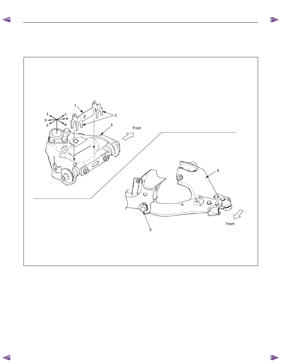
Alignment for 4
××××2 (High Ride Suspension) and 4××××4
Caster and camber adjustment
The camber angle and caster angle can be adjusted by means of the camber shims and caster shims installed in
position between the chassis frame and fulcrum pins.
RTW340LF001901
Legend
1. Camber shim
2. Caster shim
3. Upper link ASM LH
4. Lower link ASM LH
5. Adjusting cam

FRONT ALIGNMENT 3A-11
Adjustment Method
addition / subtraction of shim
front side
rear side
move direction
of upper b/j
caster angle
alteration
camber angle alteration
addition subtraction
a
decrease
decrease (toward
negative direction)
subtraction addition
b
increase
increase (toward positive
direction)
no change
subtraction
c
decrease
no alteration
caster
adjustment
no change
addition
d
increase
no alteration
addition e
no
alteration
decrease (toward
negative direction)
camber
adjustment
subtraction f
no
alteration
increase (toward positive
direction)
Notes:
1. Adjusting cam is at initial position (the hole & projection
are upward as shown in a illustration) before a shim
adjustment.
2. Difference of caster shim front/rear thickness should be
3.6mm(0.142in) or less.
Overall thickness of caster shim and camber shim
should be 10.8mm(0.426in) or less.
3. Make a combination in a such a way that the number of
shims is at a minimum.
Fulcrum Pin Bolt Torque
N
⋅m (kgf⋅m/lb⋅ft)
152.0
±15 (15.5±1.5 / 112.1±10.8)
CASTER
3
°10’±45’
Note:
Left and right side to be equal within 30’.
CAMBER
0
°±30’
Note:
Left and right side to be equal within 30’.
KING PIN INCLINATION
12
°30’±30’
Нет комментариевНе стесняйтесь поделиться с нами вашим ценным мнением.
Текст