Isuzu KB P190. Manual — part 377
6A-148 ENGINE MECHANICAL (4JK1/4JJ1)
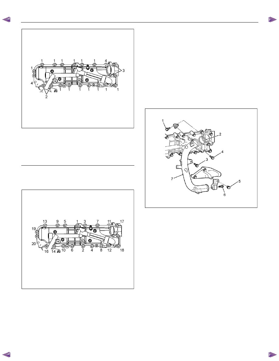
RTW56ASH013201
Legend
1. Bolt 45 mm (1.77 in)
2. Bolt 110 mm (4.33 in)
3. Bolt 70 mm (2.76 in)
4. Nut
• Tighten the bolts to the specified torque in the
order shown in the illustration.
Tightening torque: 25 N
⋅⋅⋅⋅m (2.5 kg⋅⋅⋅⋅m / 18 lb ft)
RTW56ASH013301
2. Install the water intake pipe.
a. Temporarily tighten the bolt (6).
b. Install the O-ring (2) to the water intake pipe
(7).
c. Apply soapy water to the O-ring (2) and install
the water intake pipe (7).
• Take care not to twist the O-ring.
d. Temporarily tighten the bolts.
Temporary tightening order: 1→3→4→5
e. Tighten the bolts to the specified torque.
Fully tightening order: 3→4→1→5→6
Tightening torque: 25 N
⋅⋅⋅⋅m (2.5 kg⋅⋅⋅⋅m / 18 lb ft)
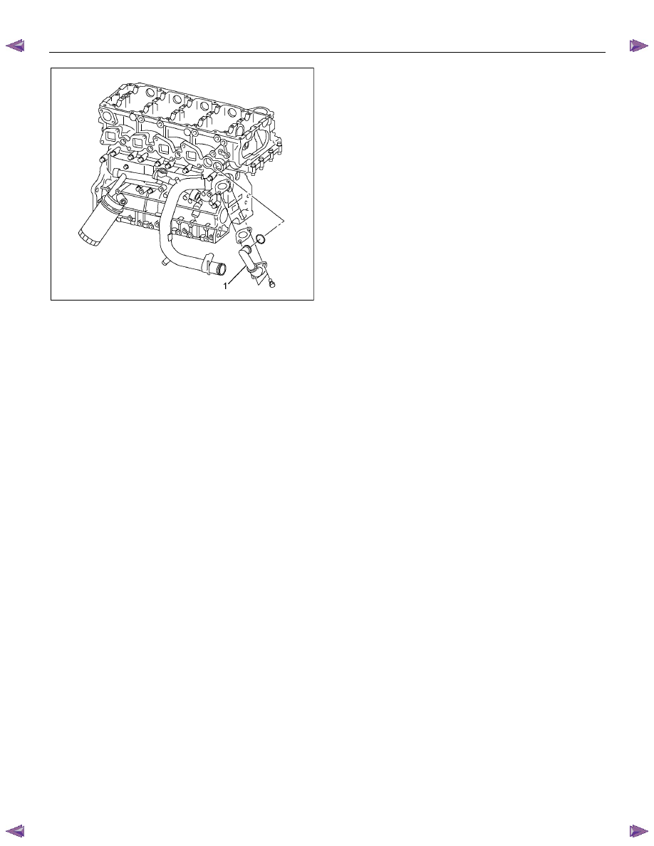
RTW76ASH001701
3. Install the water bypass pipe (1).
• After applying soapy water to O-ring, set it on
bypass pipe and insert into the cylinder head.
Tighten the bolts to the specified torque.
Tightening torque: 25 N
⋅⋅⋅⋅m (2.5 kg⋅⋅⋅⋅m / 18 lb ft)
ENGINE MECHANICAL (4JK1/4JJ1) 6A-149
RTW56ASH008401
4. Install the bracket of generator.
Tighten the bolts to the specified torque.
Tightening torque: 51 N
⋅⋅⋅⋅m (5.2 kg⋅⋅⋅⋅m / 38 lb ft)
5. Install the adjustment bracket of generator.
Tighten the bolts to the specified torque.
Tightening torque: 25 N
⋅⋅⋅⋅m (2.5 kg⋅⋅⋅⋅m / 18 lb ft)
6. Install the generator.
Refer to Installation procedure for generator in this
manual.
7. Install the exhaust manifold.
Refer to Installation procedure for turbocharger
and exhaust manifold in this manual.

6A-150 ENGINE MECHANICAL (4JK1/4JJ1)
Crank Case and Oil Pan
Components
RTW76ALF000801
Legend
1. Gasket
2. Oil
Strainer
3. Bolt
4. Crank
Case
5.
Rear
Plate
6. Bolt
7. Oil
Pan
8. Bolt
ENGINE MECHANICAL (4JK1/4JJ1) 6A-151
Removal
1. Remove the engine assembly.
Refer to “Engine Assembly”.
2. Remove the oil level gage guide tube.
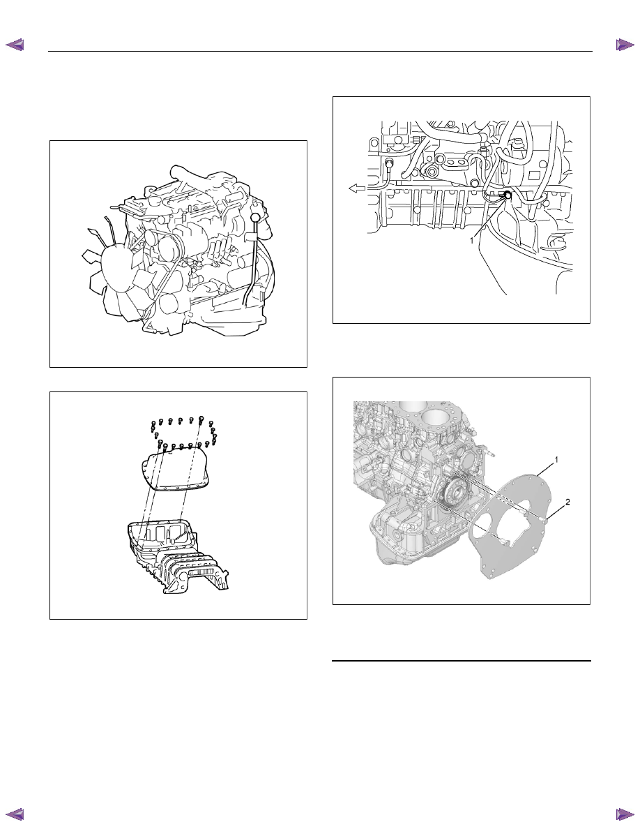
RTW56ASH015601
3. Remove the oil pan.
RTW56ASH015001
4. Disconnect the earth terminal (1) of crank case
side.
RTW76ASH001801
5. Remove the flywheel.
Refer to “Flywheel”.
6. Remove the rear plate.
RTW76ASH001901
Legend
1. Rear
Plate
2. Bolt
Нет комментариевНе стесняйтесь поделиться с нами вашим ценным мнением.
Текст