Isuzu KB P190. Manual — part 376
6A-144 ENGINE MECHANICAL (4JK1/4JJ1)
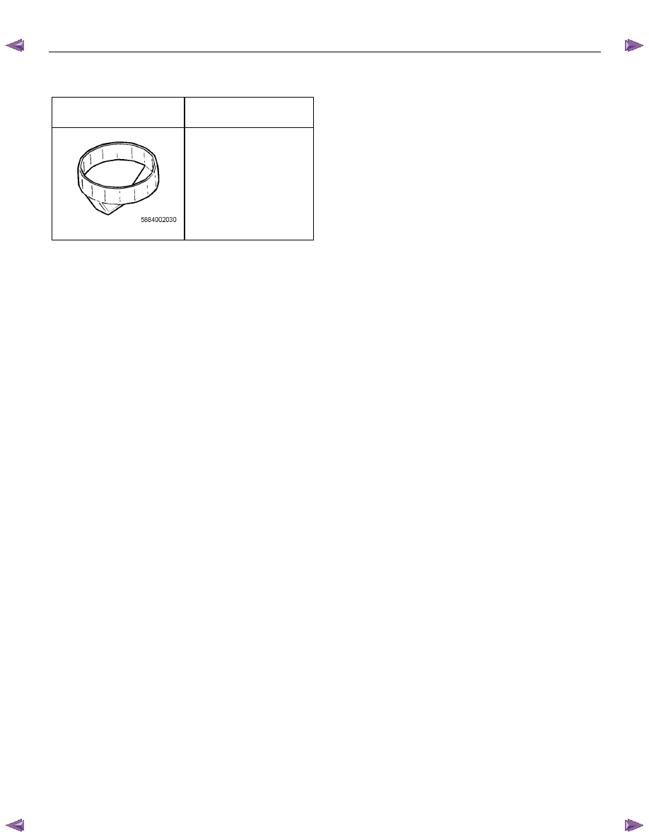
Special Tools
ILLUSTRATION
PART NO.
PART NAME
5-8840-0203-0
Oil filter wrench
ENGINE MECHANICAL (4JK1/4JJ1) 6A-145
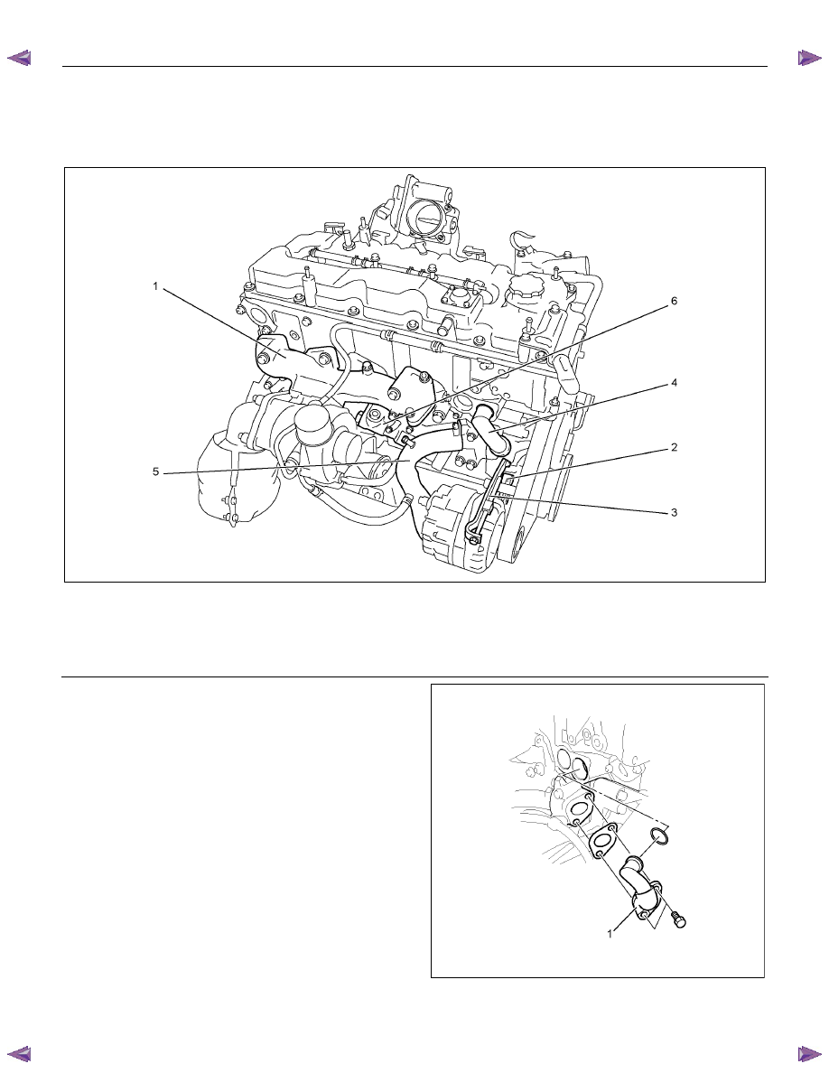
Oil Filter Assembly and Oil Cooler
Components
RTW56AMF000401
Legend
1. Exhaust
Manifold
2. Generator
Bracket
3. Generator Adjustment Bracket
4. Water Bypass Pipe
5. Water Intake Pipe
6. Oil Filter Assembly and Oil Cooler
Removal
1. Remove the exhaust manifold.
Refer to removal procedure for "Turbocharger and
Exhaust Manifold" in this manual.
2. Remove the generator.
Refer to removal procedure for generator in this
manual.
3. Remove the adjustment bracket of generator.
4. Remove the bracket of generator.
5. Remove the water bypass pipe (1).
RTW56ASH008401
6A-146 ENGINE MECHANICAL (4JK1/4JJ1)
6. Remove the water intake pipe.
RTW56ASH012601
Legend
1. Water Intake Pipe
2. Bracket
3. Bracket
4. Bolt
7. Remove the oil cooler.
RTW66ASH009101
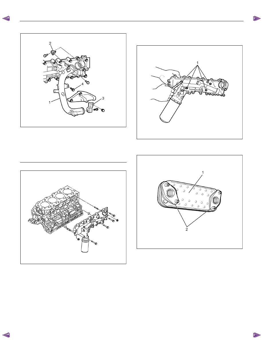
Disassembly
1. Remove the element mounting nut (1).
RTW56ASH012901
2. Remove the element (1).
3. Remove the gasket (2).
RTW56ASH013001
ENGINE MECHANICAL (4JK1/4JJ1) 6A-147
Reassembly
1. Install the gasket on the element.
2. Install the element.
3. Tighten the element fixing nut using the specified
torque.
Tightening torque: 25 N
⋅⋅⋅⋅m (2.5 kg⋅⋅⋅⋅m / 18 lb ft)
Installation
1. Install the oil filter and cooler.
• Install the O-ring on the oil filter and cooler,
apply grease.
• Apply the liquid gasket and mount within 5
minutes. Apply liquid gasket (ThreeBond TB-
1207C or equivalent) to the flange surface
groove (cylinder block). Bead diameter must
be between 2 and 3 mm (0.079 and 0.118 in).
Refer to the illustration for the offset position
(no more than 1 mm (0.004 in)).
RTW56ASH013101
Legend
1. Liquid
Gasket
2. O-ring
• Align the oil filter and cooler holes with the
cylinder block studs. Install the oil cooler to the
cylinder clock.
Нет комментариевНе стесняйтесь поделиться с нами вашим ценным мнением.
Текст