Isuzu KB P190. Manual — part 600
6E–230
ENGINE DRIVEABILITY AND EMISSIONS
6
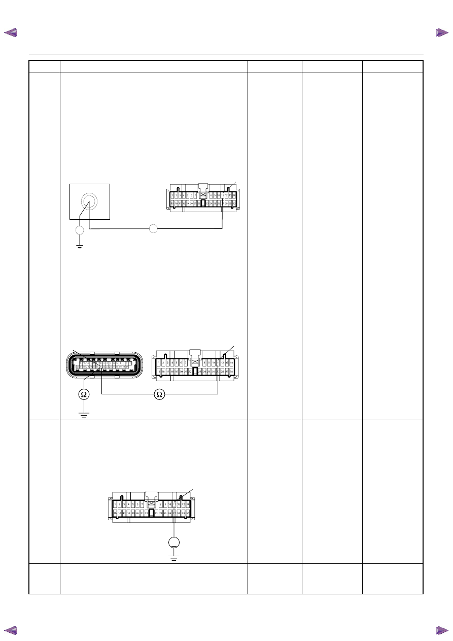
Using the DVM and check the Tacho output circuit.
Breaker box is available:
1. Ignition “Off”, engine “Off”.
2. Install the breaker box as type A. (ECM
disconnected) Refer to 6E-88 page.
3. Disconnect the meter connector.
4. Check the circuit for open or short to ground
circuit.
Was the problem found?
Breaker box is not available:
1. Ignition “Off”, engine “Off”.
2. Disconnect the ECM connector.
3. Disconnect the meter connector.
4. Check the circuit for open or short to ground
circuit.
Was the problem found?
—
Repair faulty
harness and
verify repair
Go to Step 7
7
Using the DVM and check the Tacho output circuit.
1. Ignition “On”, engine “Off”.
2. Disconnect the meter connector.
3. Check the circuit for short to power supply circuit.
Was the DVM indicated specified value?
Less than 1V
Go to Step 8
Repair faulty
harness and
verify repair
8
Check any accessory parts which may cause electric
interference or magnetic interference.
Was the problem found?
—
Remove the
accessory parts
and verify repair
Go to Step 9
Step
Action
Value(s)
Yes
No
J2-25
Breaker Box
B-24
11
Ω
Ω
11
25
C-56(J2)
B-24
V
B-24
11

ENGINE DRIVEABILITY AND EMISSIONS
6E–231
9
Replace the Tacho meter.
Was the problem solved?
—
Verify repair
Go to Step 10
10
Is the ECM programmed with the latest software
release?
If not, download the latest software to the ECM using
the “SPS (Service Programming System)”.
Was the problem solved?
—
Verify repair
Go to Step 11
11
Replace the ECM.
Is the action complete?
IMPORTANT: The replacement ECM must be
programmed. Refer to section of the Service
Programming System (SPS) in this manual.
Following ECM programming, the immobilizer system
(if equipped) must be linked to the ECM. Refer to
section 11 “Immobilizer System-ECM replacement” for
the ECM/Immobilizer linking procedure.
—
Verify repair
—
Step
Action
Value(s)
Yes
No
6E–232
ENGINE DRIVEABILITY AND EMISSIONS
SYMPTOM DIAGNOSIS
PRELIMINARY CHECKS
Before using this section, perform the “On-Board
Diagnostic (OBD) System Check” and verify all of the
following items:
• The engine control module (ECM) and malfunction
indicator lamp (MIL = Check Engine Lamp) are
operating correctly.
• There are no Diagnostic Trouble Code(s) stored.
• Tech 2 data is within normal operating range. Refer to
Typical Scan Data Values.
• Verify the customer complaint and locate the correct
symptom in the table of contents. Perform the
procedure included in the symptom chart.
VISUAL/PHYSICAL CHECK
Several of the symptom procedures call for a careful
visual/physical check. This can lead to correcting a
problem without further checks and can save valuable
time. This check should include the following items:
• ECM grounds for cleanliness, tightness and proper
location.
• Vacuum hoses for splits, kinks, and proper
connection, shown on the “Emission Control System
Schematics”. Check thoroughly for any type of leak or
restriction.
• Air intake ducts for collapsed or damaged areas.
• Air leaks at throttle body mounting area, manifold
absolute pressure (MAP) sensor and intake manifold
sealing surfaces.
• Ignition wires for cracking, harness, and carbon
tracking.
• Wiring for proper connections, pinches and cuts.
INTERMITTENT
Important: An intermittent problem may or may not turn
on the malfunction indicator lamp (MIL) or store a
Diagnostic Trouble Code. Do NOT use the Diagnostic
Trouble Code (DTC) charts for intermittent problems.
The fault must be present to locate the problem.
Most intermittent problems are cased by faulty electrical
connections or wiring. Perform a careful visual/physical
check for the following conditions.
• Poor mating of the connector halves or a terminal not
fully seated in the connector (backed out).
• Improperly formed or damaged terminal.
• All connector terminals in the problem circuit should
be carefully checked for proper contact tension.
• Poor terminal-to-wire connection. This requires
removing the terminal form the connector body to
check.
• Ignition coils shorted to ground and arcing at ignition
wires or plugs.
• MIL (Check Engine Lamp) wire to ECM shorted to
ground.
• Poor ECM grounds. Refer to the ECM wiring
diagrams.
Road test the vehicle with a Digital Multimeter
connected to a suspected circuit. An abnormal voltage
when the malfunction occurs is a good indication that
there is a fault in the circuit being monitored.
Using Tech 2 to help detect intermittent conditions. The
Tech 2 has several features that can be used to located
an intermittent condition.
An intermittent MIL (Check Engine Lamp) with no stored
Diagnostic Trouble Code may be caused by the
following:
• Ignition coil shorted to ground and arcing at ignition
wires or plugs.
• MIL (Check Engine Lamp) wire to ECM short to
ground.
• Poor ECM grounds. Refer to the ECM wiring
diagrams.
Check for improper installation of electrical options such
as light, cellular phones, etc. Check all wires from ECM
to the ignition control module for poor connections.
Check for an open diode across the A/C compressor
clutch and check for other open diodes (refer to wiring
diagrams in Electrical Diagnosis).
If problem has not been found, refer to ECM connector
symptom tables.
• Check the “Broadcast Code” of the ECM, and
compare it with the latest Isuzu service bulletins and/
or Isuzu EEPROM reprogramming equipment to
determine if an update to the ECM’s reprogrammable
memory has been released.
To check the “Broadcast Code”, connect the Tech 2,
then look for “ID info.” then select “Broadcast Code”.
This should display a 4 character code, such as “XBYA”
(example only).
This identifies the contents of the reprogrammable
software and calibration contained in the ECM.
If the “Broadcast Code” is not the most current
available, it is advisable to reprogram the ECM’s
EEPROM memory, which may either help identify a
hard-to find problem or may fix the problem.
The Service Programming System (SPS) will not allow
incorrect software programming or incorrect calibration
changes.

ENGINE DRIVEABILITY AND EMISSIONS
6E–233
ENGINE CRANKS BUT WILL NOT RUN
DEFINITIONS: Engine cranks, but will not run. (The engine never start.)
NOTE: The replacement ECM must be programmed. Refer to section of the Service Programming System (SPS) in
this manual. Following ECM programming, the immobilizer system (if equipped) must be linked to the ECM.
Refer to section 11 “Immobilizer System-ECM replacement” for the ECM/Immobilizer linking procedure.
NOTE: The vehicle with immobilizer system, this system may be activated. Check the immobilizer system diagosis.
Step
Action
Value(s)
Yes
No
1
Was the “On-Board Diagnostic (OBD) System Check”
performed?
—
Go to Step 2
Go to OBD
System Check
2
1. Perform a bulletin search.
2. If a bulletin that addresses the symptom is found,
correct the condition as instructed in the bulletin.
Was a bulletin found that addresses the symptom?
—
Verify repair
Go to Step 3
3
Was a visually/physical check performed?
—
Go to Step 4
Go to Visual /
physical Check.
4
Check the “Ignition coil” fuse (15A) and “ECM” fuse
(15A).
Was a fuse blown?
—
Verify repair
Go to Step 5
5
1. Ignition ON
2. Use a DVM to verify that battery voltage at the
ignition coil fuse, and the ECM fuse.
Was battery voltage presented at the fuses?
—
Go to Step 6
Verify & repair
6
1. Visually/physically inspect for the following
conditions:
• Restriction of air intake system. Check for a
restricted air filter element, or foreign objects
blocking the air intake system.
• Check for objects blocking the IAC passage or
throttle bore, excessive deposits in the throttle
bore and on the throttle plate.
• Check for a condition that causes a large
vacuum leak, such as an incorrectly installed or
faulty crankcase ventilation hose/brake booster
hose.
Was a problem found?
—
Verify repair
Go to Step 7
7
1. Using a Tech 2, display the IAC value.
2. Check for a faulty, plugged, or sticking IAC
operation.
Was the problem found?
—
Verify repair
Go to Step 8
8
1. Using a Tech 2, display the MAP sensor value.
2. Check for a faulty, plugged, or incorrectly installed
MAP sensor.
Was the problem found?
—
Verify repair
Go to Step 9
9
If oscilloscope is available, check the wave form of the
CKP signal.
Was the correct wave form found?
—
Go to Step 12
Go to Step 10
10
Check the CKP sensor wire for open or short circuit.
Was a problem found?
—
Verify repair
Go to Step 11
11
Replace CKP sensor.
Is there still problem?
—
Replace pulsar
ring.
Verify repair
Нет комментариевНе стесняйтесь поделиться с нами вашим ценным мнением.
Текст