Isuzu KB P190. Manual — part 334
EXHAUST SYSTEM 6F – 3
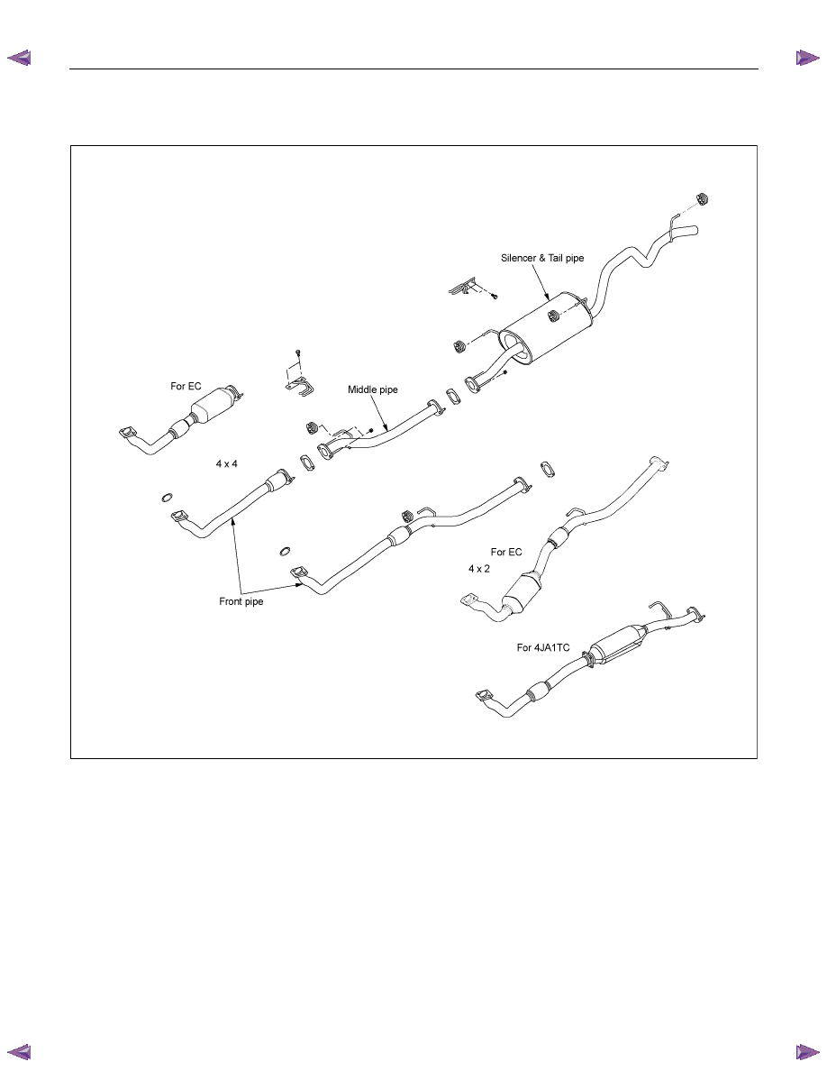
GENERAL DESCRIPTION
RTW46FLF000201
The exhaust pipe layout is described in the above illustration.
The catalytic coverter is installed between the turbocharger and the front pipe.
6F – 4 EXHAUST SYSTEM
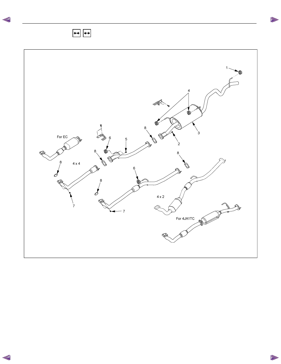
REMOVAL AND INSTALLATION
RTW46FLF000101
Removal Steps
1. Rear hanger rubber
2. Silencer front nut
3. Exhaust silencer
4. Silencer hanger rubber
5. Middle pipe nut
6. Front hanger rubber
7. Front pipe nut
8. Exhaust pipe gasket

EXHAUST SYSTEM 6F – 5
Important Operations – Installation
Follow the removal procedure in the reverse order to
perform the installation procedure. Pay careful attention to
the important points during the installation procedure.
1. Front Pipe Nut
Connect the exhaust pipe to the catalytic converter.
Torque N
⋅m (kg⋅m/lb⋅ft)
67 (6.8/49)
2. Middle pipe Nut (4
××××4 only)
Connect the middle pipe to the front pipe.
Torque N
⋅m (kg⋅m/lb⋅ft)
43 (4.4/32)
3. Silencer Front Nut
Connect the silencer to the front or middle pipe.
Torque N
⋅m (kg⋅m/lb⋅ft)
43 (4.4/32)

6F – 6 EXHAUST SYSTEM
INSPECTION AND REPAIR
Make the necessary adjustments, repairs, and part replacements if excessive wear or damage is discovered during
inspection.
Front Exhaust Pipe
Exhaust Silencer
Check the pipes for corrosion, cracking, damage or
misalignment and repair as required.
Check the rubber rings for deterioration or damage and repair
as required.
Catalytic Converter
1. Inspect outside the catalytic converter for any hitting mark.
2. Visual check inside the catalytic converter for crack or break
converter element.
3. If find any problem during the inspection, replace the
catalytic converter assembly.
Нет комментариевНе стесняйтесь поделиться с нами вашим ценным мнением.
Текст