Isuzu KB P190. Manual — part 333
6E-298 Engine Control System (4JH1)
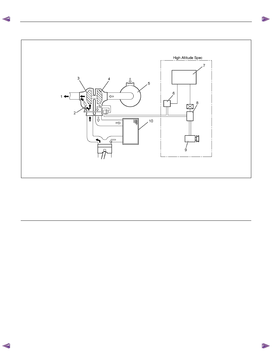
Turbocharger Description
RTW66EMF000501
Legend
1. Exhaust
Gas
2. Wastegate
Valve
3. Turbine
Wheel
4. Compressor
Wheel
5. Air
Cleaner
6. Vacuum Pressure Sensor
7. Engine Control Module (ECM)
8. Turbocharger Solenoid Valve
9. Vacuum Pump (ACG)
10. Change Air Cooler (Intercooler)
The turbocharger is used to increase the amount of air
that enters the engine cylinders. This allows a
proportional increase of fuel to be injected into the
cylinders, resulting in increased power output, more
complete combustion of fuel, and increased cooling of
the cylinder heads, pistons, valves, and exhaust gas.
This cooling effect helps extend engine life.
Heat energy and pressures in the engine exhaust gas
are utilized to drive the turbine. Exhaust gas is directed
to the turbine housing. The turbine housing acts as a
nozzle to direct the shaft wheel assembly. Since the
compressor wheel is attached directly to the shaft, the
compressor wheel rotates at the same speed as the
turbine wheel. Clean air from the air cleaner is drawn
into the compressor housing and wheel. The air is
compressed and delivered through a crossover pipe to
the engine air intake manifold, then into the cylinders.
The amount of air pressure rise and air volume
delivered to the engine from the compressor outlet is
regulated by a wastegate valve in the exhaust housing.
The position of the wastegate valve is controlled by the
amount of pressure built up on the intake side of the
turbocharger. The diaphragm on the inside of the
wastegate is pressure sensitive, and controls the
position of the valve inside the turbocharger. The
position of the valve will increase or decrease the
amount of boost to the turbocharger.
The charge air cooler also helps the performance of the
diesel. Intake air is drawn through the air cleaner and
into the turbocharger compressor housing. Pressurized
air from the turbocharger then flows forward through the
charge air cooler located in the front of the radiator.
From the charge air cooler, the air flows back into the
intake manifold.
The charge air cooler is a heat exchanger that uses air
flow to dissipate heat from the intake air. As the
turbocharger increases air pressure, the air temperature
increases. Lowering the intake air temperature
increases the engine efficiency and power by packing
more air molecules into the same space.
Engine Control System (4JH1) 6E-299
Special Tools and Equipment
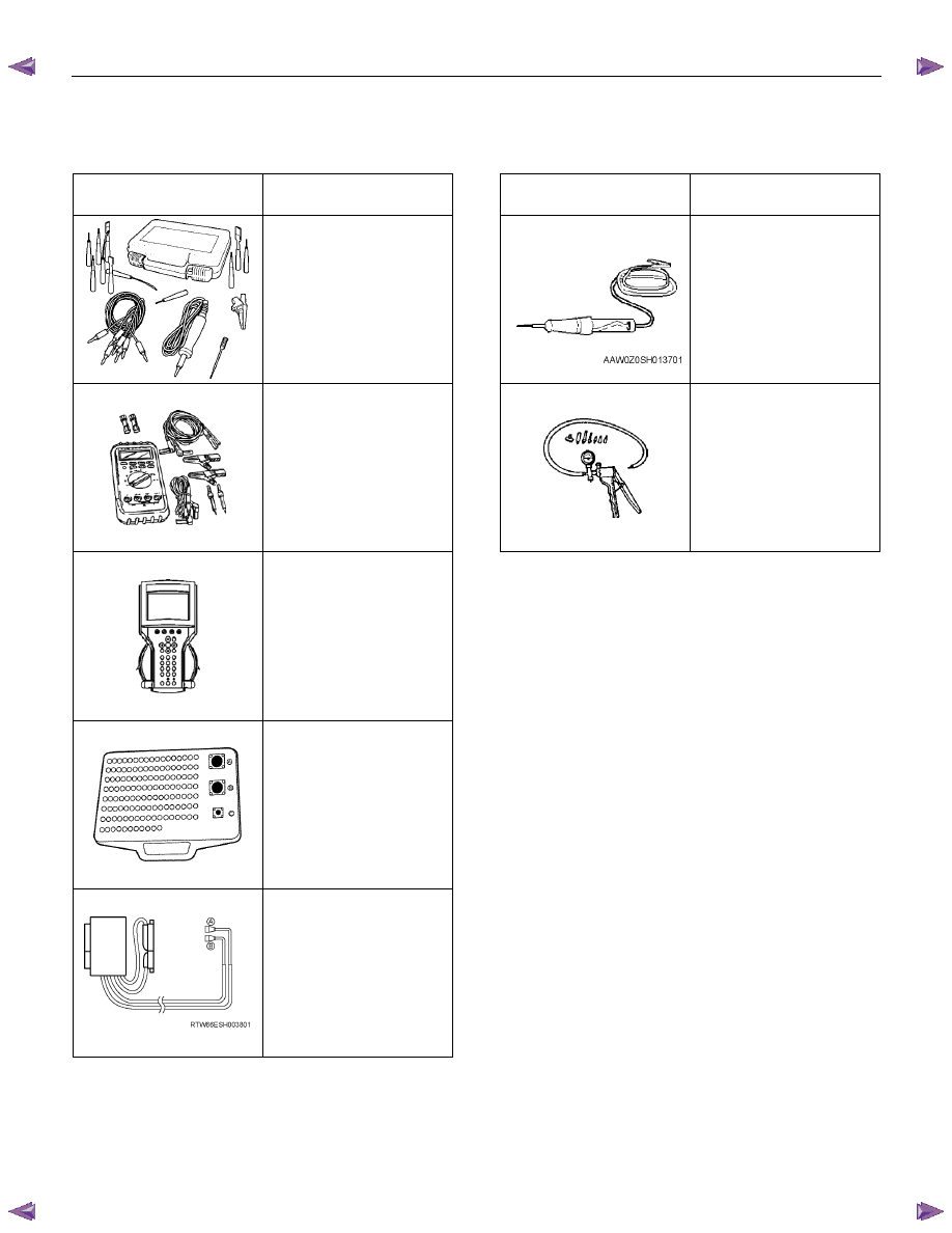
Special Tools and Equipment
Illustration
Tool Number/
Description
Illustration
Tool Number/
Description
5-8840-2835-0 /
J-35616-A
Connector Test Adapter
Kit
(With Test Lamp)
5-8840-0607-0 /
J-34142-B
Test Lamp
5-8840-0285-0 /
J-39200
Digital Multimeter
5-8840-0279-0 /
J-23738-A
Vacuum Pump
Tech2 Kit
Breaker Box
Adapter Harness
SECTION 6F
EXHAUST SYSTEM
TABLE OF CONTENTS
PAGE
Main Data and Specifications. . . . . . . . . . . . . . . . . . . . . . ... 6F - 2
General Description . . . . . . . . . . . . . . . . . . . . . . . . . . .. 6F - 3
Removal and Installation . . . . . . . . . . . . . . . . . . . . . . . . .. 6F - 4
Inspection and Repair . . . . . . . . . . . . . . . . . . . . . . . . . ... 6F - 6
General Description . . . . . . . . . . . . . . . . . . . . . . . . . . .. 6F -7
EGR System Diagram. . . . . . . . . . . . . . . . . . . . . . . . . . 6F 9
Inspection . . . . . . . . . . . . . . . . . . . . . . . . . . . . . . .. 6F-11
EGR Cooler (4JA1TC/4JH1TC Euro-III model). . . . . . . . . . . . . . . . . 6F-12
Turbocharger . . . . . . . . . . . . . . . . . . . . . . . . . . . . . . 6F -15
Main Data and Specifications. . . . . . . . . . . . . . . . . . . . . ... 6F -15
General Description . . . . . . . . . . . . . . . . . . . . . . . . . . .. 6F -16
Inspection and Repair . . . . . . . . . . . . . . . . . . . . . . . . . ... 6F -17
Special Tools . . . . . . . . . . . . . . . . . . . . . . . . . . . . . . 6F -19
IHI Service Network . . . . . . . . . . . . . . . . . . . . . . . . . . ... 6F -20
EXHAUST SYSTEM 6F – 1
6F – 2 EXHAUST SYSTEM
MAIN DATA AND SPECIFICATIONS
Front pipe
Pipe outside diameter x thickness
mm (in)
50.8 x 1.5 (2.0 x 0.059)
For EC model, catalitic converter is
combined to the front pipe.
Middle pipe
Pipe outside diameter x thickness
mm (in)
50.8 x 1.5 (2.0 x 0.059)
Silencer & tail pipe
Type
Circular section-shell construction
of double skin and end plates,
internal construction of baffles
and perforated tubes.
Tail pipe outside diameter x thickness
mm (in)
50.8 x 1.6 (2.0 x 0.063)
Length
mm (in)
Approximately 1335 (52.6)
Mounting
Number of suspension points
4
Type
Rubber
Нет комментариевНе стесняйтесь поделиться с нами вашим ценным мнением.
Текст