Isuzu KB P190. Manual — part 332
6E-294 Engine Control System (4JH1)
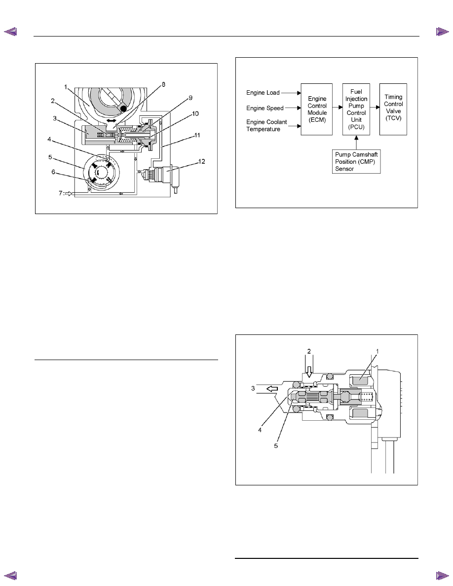
Timing Control Device Description
RTW66ESH003001
Legend
1. Cam
Ring
2. Servo
Valve
3. Timer
Piston
4. Outlet
5. Feed
Pump
6. Inlet
7. Fuel
Suction
8. Ball
Pin
9. Annular
Chamber
10. Hydraulic Stopper
11. Return Passage
12. Timing Control Valve (TCV)
The timing device determines the optimum injection
timing against variations in engine speed. The pressure
of the fuel fed from the feed pump is adjusted in
accordance with speed by the regulating valve. This
delivery pressure acts on the hydraulic stopper's
annular chamber as control pressure. The chamber
pressure of the annular chamber is controlled by the
timing control valve (TCV). The timing plunger is
connected to the cam ring by a ball pin. Axial movement
of the timing plunger is transferred to the cam ring in the
form of rotational movement. Movement to the right of
the timing plunger (to the spring side) advances
injection timing. The main components are timing
plunger, the TCV and pump camshaft position (CMP)
sensor.
Beginning of Injection Staring
RTW66ESH003101
The engine control module (ECM) contains
characteristic maps of the beginning of injection,
corresponding to engine operating conditions
(engine load, engine speed and engine coolant
temperature). The fuel injection pump control unit
(PCU) is constantly comparing the set beginning of
injection timing and the actual beginning of injection
timing. If there is a difference, the timing control
valve (TCV) is controlled by the duty ratio. (The
actual beginning of injection timing is determined
from the pump camshaft position [CMP] sensor.)
Timing Control Valve
RTW66ESH003201
Legend
1. Coil
2. From Annular Chamber
3. To Feed Pump
4. Orifice
5. Valve
Needle
Engine Control System (4JH1) 6E-295
The timing control valve (TCV) acts as a variable
throttle, using the rapid opening and closing (cycling)
of the valve needle in the TCV. At normal operation,
the TCV controls the pressure acting on the annular
chamber so that the hydraulic stopper cam move to
any position, from the retard position to the advance
position. At this time, the duty ratio is set by the fuel
injection pump control unit (PCU).
When control current flows to the TCV coil, the valve
needle opens and the fuel annular chamber flows
through the orifice to the feed pump inlet.
Consequently, the pressure of the annular chamber
decreases and the hydraulic stopper is moved to the
retard side.
When control current to the TCV coil is cut, the valve
needle closes and the return passage is closed.
Consequently, the pressure of the annular chamber
increases and the hydraulic stopper is moved to the
advance side.
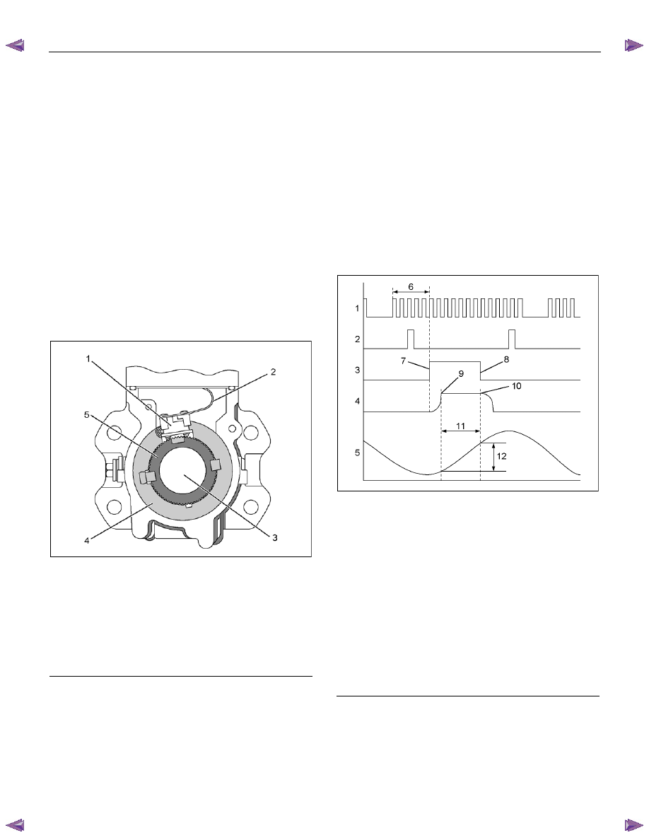
Pump Camshaft Position (CMP) Sensor
RTW66ESH003301
Legend
1. Pump Camshaft Position (CMP) Sensor
2. Flexible Connecting Harness
3. Drive
Shaft
4. Pump Camshaft Position (CMP) Sensor Retaining
Ring
5. Sensor
Wheel
When the drive shaft rotates, the pump camshaft
position (CMP) sensor receives signal form the sensor
wheel, and an electric pulse is sent through the flexible
connecting harness to the fuel injection pump control
unit (PCU). From these signals the PCU can determine
the average pump speed and the momentary pump
speed. The pump CMP sensor is mounted to the cam
ring. Thus, the relationship between the cam ring and
the pump CMP sensor signal is constant. The pump
CMP sensor signal is utilized for the following purposes:
• To determine the momentary angular position of
the cam ring.
• To calculate the actual speed of the fuel injection
pump.
• To determine the actual timing plunger position.
RTW66ESH003401
Legend
1. Pump Camshaft Position (CMP) Sensor Signal
2. Crankshaft Position (CKP) Sensor Signal
3. Fuel Injection Solenoid Valve Control Pulse
4. Fuel Injection Solenoid Needle Valve Lift
5. Cam Lift (Cam Profile)
6. Pulse
Count
7. Fuel Injection Solenoid Valve Close
8. Fuel Injection Solenoid Valve Open
9. Start of Pressure Delivery
10. End of Pressure Delivery
11. Pressure Delivery Angle
12. Effective Stroke
6E-296 Engine Control System (4JH1)
• Momentary Cam Ring Angular Position
The momentary angular position of the cam ring is
input into the fuel injection PCU as a fuel injection
solenoid valve control signal. From momentary
input of angular position for fluctuations in running
conditions, the fuel injection solenoid valve open
and close intervals corresponding to the cam ring's
cam lift can be accurately determined.
• Actual Injection Pump Speed
When the crankshaft position (CKP) sensor is
faulty, the engine control module (ECM) uses the
pump CMP signal as a replacement signal.
• Actual Timing Plunger Position
The actual timing plunger position can be
determined by comparing the CKP sensor signal
with the pump CMP sensor angle. This position is
used for timer control.

Engine Control System (4JH1) 6E-297
Exhaust Gas Recirculation (EGR) System Description
RTW66ELF000101
Legend
1. EGR
Cooler
2. Engine Coolant Outlet
3. Engine Coolant Inlet
4. EGR
Valve
5. ECM
6. MAF & IAT Sensor
7. Intake Throttle Valve
The EGR system recirculates a part of exhaust gas
back into the intake manifold, which results in reducing
nitrogen oxide (NOx) emissions. The EGR control
system uses an electronic control system solenoid valve
and vacuum control EGR valve to ensure both
driveability and low emission. The engine control
module (ECM) controls the EGR flow amount based on
the engine speed, engine coolant temperature, intake
air temperature, barometric pressure and fuel injection
quantity. The ECM controls the EGR valve opening by
controlling the EGR solenoid valve drive duty. The mass
air flow (MAF) sensor monitors EGR gas flow amount.
An expected MAF amount should be detected while the
engine running.
Нет комментариевНе стесняйтесь поделиться с нами вашим ценным мнением.
Текст