Isuzu KB P190. Manual — part 210
ENGINE MECHANICAL 6A – 35
Idling Speed Adjustment
1. Loosen the idling set screw lock nut
c
on the injection
pump idling set bolt.
2. Adjust the idling speed to the specified range by
turning the idling set bolt
d
.
3. Lock the engine set nut
c
with the idling set bolt lock
nut.
4. Check that the idling control cable is tight (free of
slack). If required, remove the slack from the cable.
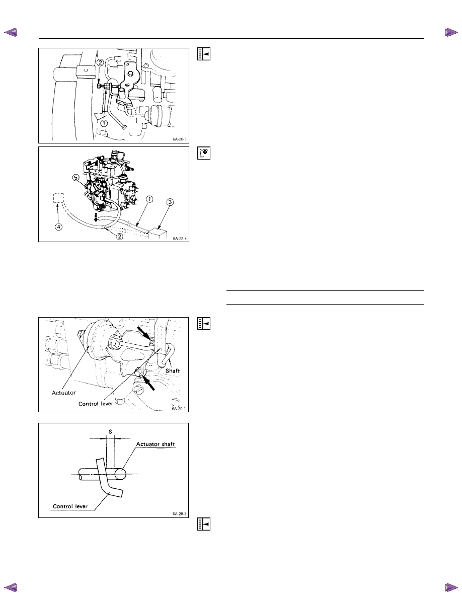
Fast Idling Speed Inspection
1. Set tachometer to the engine.
2. Disconnect the vacuum hose
c
from the fast idle
actuator
g
on the injection pump.
3. Disconnect the other vacuum hose
d
from the
vacuum switching valve
e
and connect it to the fast
idle actuator
g
.
The vacuum line will now be connected directly from
the vacuum pump
f
to the fast idle actuator.
4. Check the engine fast idling speed.
If the engine idling speed is outside the specified
range, it must be adjusted.
Fast Idling Speed
rpm
850
± 25
Fast Idling Speed Adjustment
1. Loosen the fast idle actuator bracket bolts.
2. Adjust the fast idling speed by moving the actuator
bracket, so that the clearance “S” can be 1 ~ 2 mm
(0.04 ~ 0.08 in.).
3. Tighten the bracket bolts.
Accelerator Control Cable Adjustment
Refer to Sec. 6H-6 (Accelerator Control)
6A – 36 ENGINE MECHANICAL
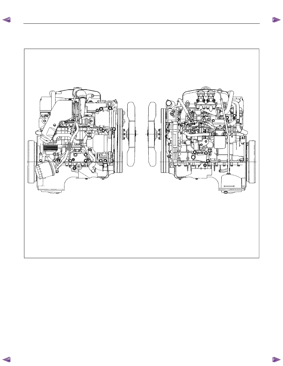
GENERAL DESCRIPTION
RTW46AMF000401
The 4J series automotive diesel engine has special designed combustion chambers in the piston. This design
provides superior fuel economy over a wide range of driving conditions.
Auto-thermatic pistons with cast steel struts are used to reduce thermal expansion and resulting engine noise when
the engine is cold.
Chrome plated dry type cylinder liners provide the highest durability.
The laminated steel sheet cylinder head gasket is very durable and, to increase the head gasket reliability.
The crankshaft has been tufftrided to provide a longer service life. Because the crankshaft is tufftrided, it cannot be
reground.
The 4JA1T(L) engine is equipped with the BOSCH VE-Type distributor injection pump.
The 4JH1TC and 4JA1TC engine is equipped with the BOSCH VP44-Type distributor injection pump.
The engine is turbocharger equipped.

ENGINE MECHANICAL 6A – 37
REMOVAL AND INSTALLATION
Read this section carefully before performing any removal and installation procedure. This section gives
you important points as well as the order of operation. Be sure that you understand everything in this section before
you begin.
Removal
P1010011
1. Battery
1) Disconnect the battery cable and the grounding cable
from the battery terminals.
2) Remove the battery clamp. Take care not to
accidentally short the battery with the wrench or some
other tool.
3) Remove the battery.
4) Disconnect the battery cable at the starter motor and
the ground cable at the cylinder body.
2. Engine Hood
Apply setting marks to the engine hood and the engine
hood hinges before removing the engine hood. This will
facilitate reinstallation of the engine hood to its original
position.
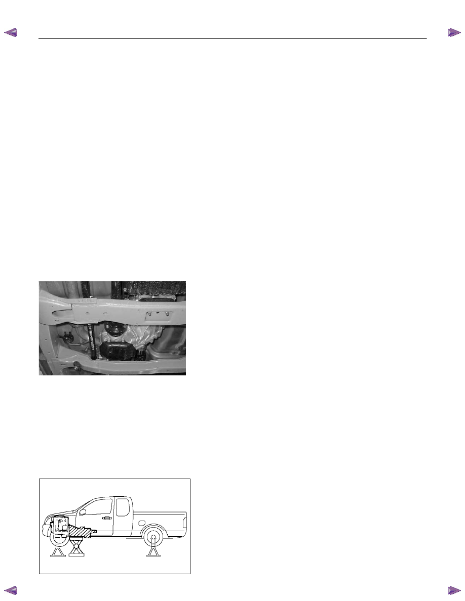
3. Supporting the Vehicle
1) Jack up the vehicle.
2) Place chassis stands at the front and the rear of the
vehicle.
4. Under cover (for 4x4 model)
5. Rear propeller shaft
1) Remove the propeller shaft flange yoke at the rear
differential.
2) Remove the center bearing retainer bolts.
3) Remove the propeller shaft together with the center
bearing from the transmission mainshaft spline.
F06R300006
P1010002
6A – 38 ENGINE MECHANICAL
6. Front propeller shaft (for 4x4 model)
Remove the spline yoke flange bolt at the transfer output
shaft.
Do not allow the spline yoke to fall away from the front
propeller shaft.
If the spline yoke should fall away from the front propeller
shaft, align the setting marks on the spline yoke and the
propeller shaft to reassemble the two marks. The setting
marks are punched circles approx. 3mm (0.12 in) in
diameter.
7. Clutch slave cylinder (for M/T model)
8. ATF pipe (for A/T model)
9 Shift control cable (for A/T model)
10. Transmission sensor harness
Remove the vehicle speed sensor connector, inhibitor
switch connector (A/T), ATF temperature sensor
connector, back up light switch connector (M/T) from
transmission.
11. Breather hose (for A/T model)
12. Transmission shift lever (for M/T model)
Remove the shift lever from the floor.
13. Transfer shift lever (for 4x4 model)
Remove the shift lever from the floor.
14. Transmission member
1) Support the transmission with the transmission jack.
2) Remove the transmission member mounting bolts
fixing the transmission member to the chassis frame.
15. Torque converter bolt (for A/T model)
1) Remove the under cover under the torque converter
housing.
2) Rotate the flywheel by using tire lever or some other
tool, and then remove the torque converter bolts.
16. Transmission coupling bolt
1) Support the engine with the garage jack.
2) Use the jack to slightly lower the transmission.
3) Remove the transmission coupling bolts.
17. Transmission (and transfer)
Separate the transmission (and transfer) from the
engine.Take care not to damage the transmission, the
engine, and their related parts..
F06R300007
P1010025
Нет комментариевНе стесняйтесь поделиться с нами вашим ценным мнением.
Текст