Isuzu KB P190. Manual — part 211
ENGINE MECHANICAL 6A – 39
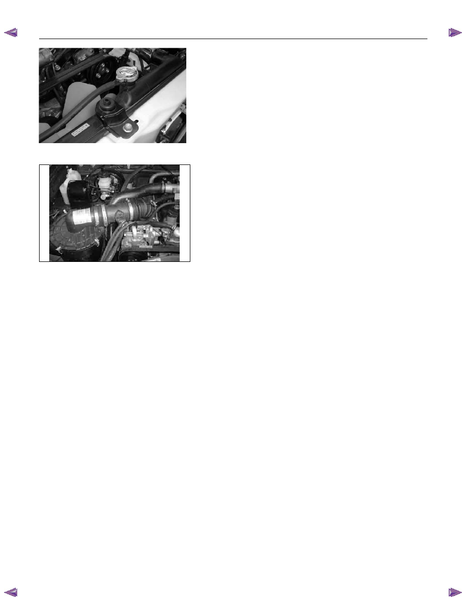
18. Radiator
1) Drain the engine coolant.
2) Remove the reservoir hose.
3) Remove the upper and lower hose.
4) Remove the fan guide.
5) Remove the radiator.
19. Fan
P1010034
20. Air cleaner
1) Remove the MAF sensor connector (4JA1TC/4JH1TC)
from air cleaner duct.
2) Remove the air cleaner duct and the air cleaner box
from engine room.
3) Remove the two air ducts from inter cooler
(4JA1TC/4JH1TC).
21. Power Steering Pump
Loosen the power steering pump adjust plate bolt, then
remove the power steering pump assembly. Place the
power steering pump assembly along with piping on the
body side.
22. Air conditioner compressor
1) Remove air compressor magnet connector.
2) Remove the air conditioner compressor. Place the air
conditioner compressor along with piping on the body
side.
23. Engine Control Cable
Remove the engine control cable from its bracket
(4JA1TC/4JH1TC) or the injection pump (4JA1T(L)).
24. Vacuum Piping
Remove the vacuum pipe from the vacuum pump, the
EGR valve, injection pump FICD (4JA1T(L)).
25. Engine Harness
1) Remove following connectors from engine.
• TPS
connector
• Oil pressure switch connector
• Thermo switch connector
• Injection pump connector
• Engine
earth
• Thermometer unit connector
• TDC
sensor
2) Remove the clips fixing engine harness.
P1010009
6A – 40 ENGINE MECHANICAL
140R300001
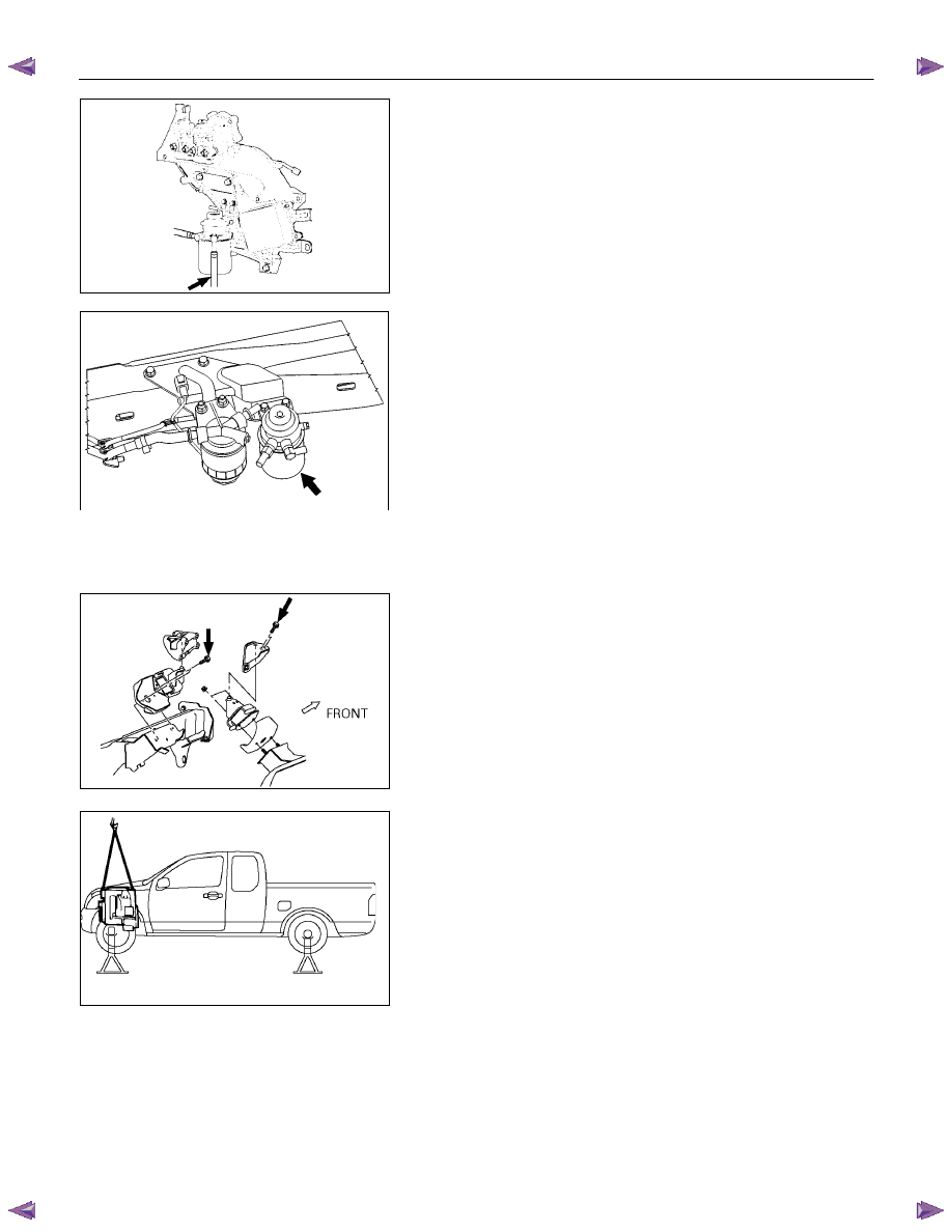
26. Fuel Hose
Remove the fuel hose from the fuel filter (Except EURO
III).
RTW46ASH000501
Remove the fuel hose from injection pump (EURO III
only).
27. Exhaust Pipe
Remove the front exhaust pipe bolts and separate the
exhaust manifold and the front exhaust pipe.
28. Engine Assembly
1) Remove two right side engine foot bolts.
2) Remove two left side engine mount bolts.
3) Use the hoist to lift the engine from the engine
compartment.
Installation
To reassemble, follow the removal steps in the reverse
order.
022R300002
F06R300008
ENGINE MECHANICAL 6A – 41
Coolant Replenishment
Warning:
When the coolant is heated to a high temperature, be
sure not to loosen or remove the rediator cap.
Otherwise you might get scalded by hot vapor or
boiling water.
To open the radiator cap, put a piece of thick cloth on
the cap and loosen the cap slowly to reduce the
pressure when the coolant has become cooler.
1. Open rediator cap pour coolant up to filler neck
2. Pour coolant into reservoir tank up to "MAX" line
3. Tighten radiator cap and start the engine. After idling
for 2 to 3 minutes, stop the engine and reopen radiator
cap. If the water level is lower, replenish.
4. After replenish the coolant tighten radiator cap, warm
up the engine at about 2000 rpm. Set heater
adjustment to the highest temperature position, and let
the coolant circulate also into heater water system.
5. Check to see the thermometer, continuously idling 5
minutes and stop the engine.
6. When the engine has been cooled, check filler neck for
water level and replenish if required. Should extreme
shortage of coolant is found, check the coolant system
and reservoir tank hose for leakage.
7. Pour coolant into the reservoir tank up to "MAX" line.
Coolant Capacity
lit (US/UK gal)
4JA1 / TC
9.4 (2.5 / 2.1)
4JH1TC
M/T: 10.1 (2.7 / 2.2)
A/T: 10.0 (2.6 / 2.2)
Engine Warm-Up
After completing the required maintenance procedures,
start the engine and allow it to idle until it is warm.
Check the following:
1. Engine idling speed.
2. Engine noise level.
3. Engine lubricating system and cooling system.
Carefully check for oil and coolant leakage.
4. Clutch
engagement.
5. Transmission
operation.
6. Indicator warning light operation.
6A – 42 ENGINE MECHANICAL
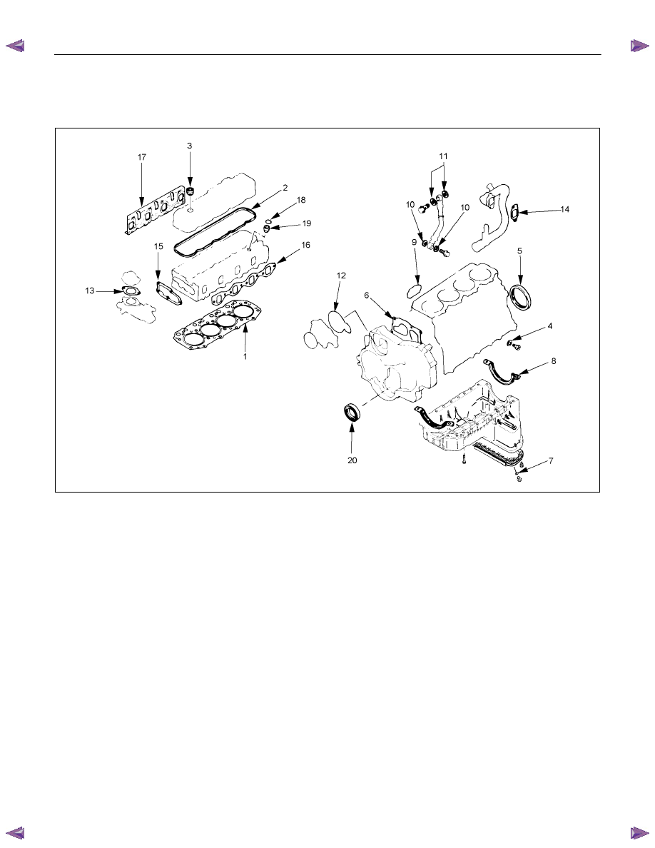
ENGINE REPAIR KIT
RTW36ALF000601
Removal Steps
1. Cylinder head gasket
2. Head cover gasket
3. Head cover cap nut gasket
4. Drain cock gasket
5. Crankshaft rear oil seal
6. Gear case gasket
7. Oil pan drain plug gasket
8. Oil pan gasket
9. Oil filter gasket
10. Joint bolt gasket
11. Vacuum pump gasket
12. Water pump O-ring
13. Water outlet pipe gasket
14. Intake pipe gasket
15. Thermostat housing gasket
16. Intake manifold gasket
17. Exhaust manifold gasket
18. Nozzle holder O-ring
19. Nozzle holder gasket
20. Crankshaft front oil seal
NOTE
Discard all O-rings, gaskets, and seals removed at disassembly and replace them with new ones. Reuse of
these parts will result in oil, water, and gas leakage.
Нет комментариевНе стесняйтесь поделиться с нами вашим ценным мнением.
Текст