Isuzu KB P190. Manual — part 209
ENGINE MECHANICAL 6A – 31
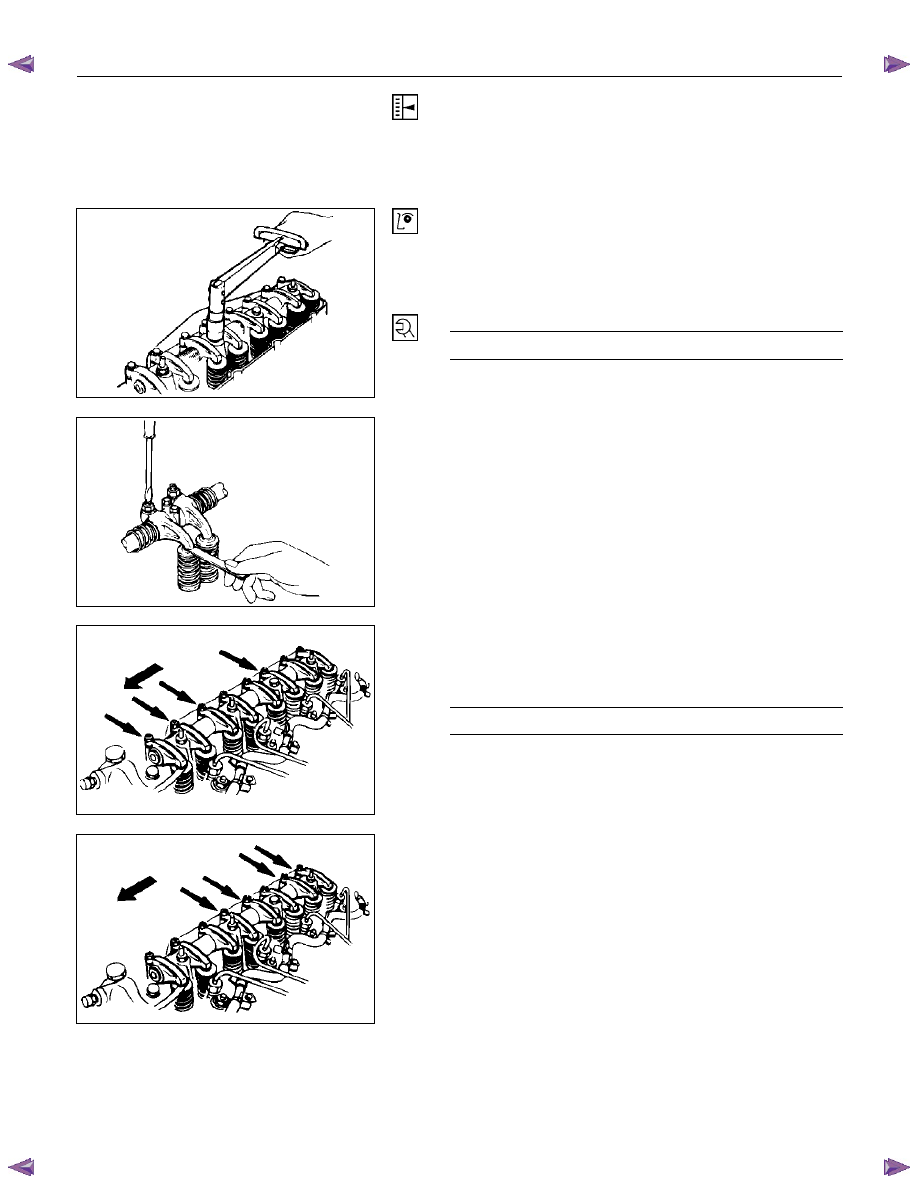
VALVE CLEARANCE ADJUSTMENT
1. Bring the piston in either the No. 1 cylinder or the No. 4
cylinder to TDC on the compression stroke by turning
the crankshaft until the crankshaft damper pulley TDC
line is aligned with the timing pointer.
014RY00014
2. Check the rocker arm shaft bracket nuts for
looseness.
Tighten any loose rocker arm shaft bracket nuts
before adjusting the valve clearance.
Rocker Arm Shaft Bracket Nut Torque
N·m (kg·m /lb·ft)
54 (5.5/40)
014RY00015
8. Check for play in the No. 1 intake and exhaust valve
push rods.
If the No. 1 cylinder intake and exhaust valve push
rods have play, the No. 1 piston is at TDC on the
compression stroke.
If the No. 1 cylinder intake and exhaust valve push
rods are depressed, the No. 4 piston is at TDC on the
compression stroke.
014RY00016
Adjust the No.1 or the No. 4 cylinder valve clearances
while their respective cylinders are at TDC on the
compression stroke.
Valve Clearance (At Cold)
mm (in)
0.4 (0.016)
9. Loosen each valve clearance adjusting screw as
shown in the illustration.
10. Insert a feeler gauge of the appropriate thickness
between the rocker arm and the valve stem end.
014RY00017
11. Turn the valve clearance adjusting screw until a slight
drag can be felt on the feeler gauge.
12. Tighten the lock nut securely.
13. Rotate the crankshaft 360
°.
14. Realign the crankshaft damper pulley TDC notched
line with the timing pointer.
15. Adjust the clearances for the remaining valves as
shown in the illustration.
6A – 32 ENGINE MECHANICAL
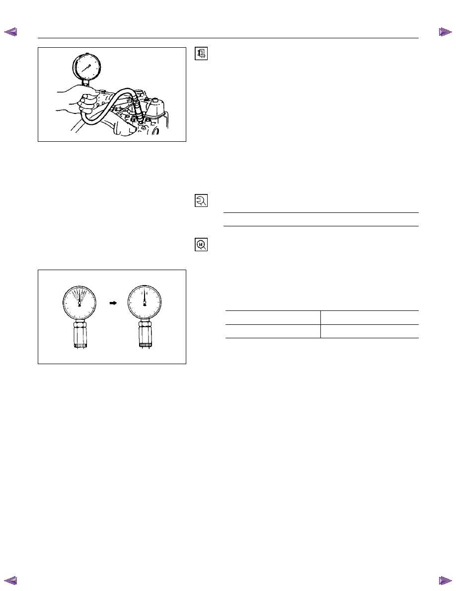
COMPRESSION PRESSURE
MEASUREMENT
1. Start the engine and allow it to idle until the coolant
temperature reaches 70 – 80
°C (158 – 176 °F).
2. Remove the following parts.
• Leak off pipe
• Injection nozzle holder bracket
• Injection nozzle holder
3. Install the following parts.
• Set the adapter and compression gauge (SST) to
the No.1 cylinder injection nozzle hole.
• Injection nozzle holder bracket
Injection nozzle holder bracket Bolt Torque
N·m (kg·m /lb·ft)
37 (3.8/27)
Compression Gauge: 5-8840-2675-0
Adapter; Compression Gauge: 5-8531-7001-0
4. Turn the engine over with the starter motor and take
the compression gauge reading.
Compression Pressure
MPa (kg/cm
2
/psi) at 200 rpm
Standard Limit
3.0 (31.0/441)
2.1 (21.7/309)
5. Repeat the procedure (Steps 3 and 4) for the
remaining cylinders.
If the measured value is less than the specified limit,
refer to “Troubleshooting” in this Manual.
F06XL056
901R100003
ENGINE MECHANICAL 6A – 33
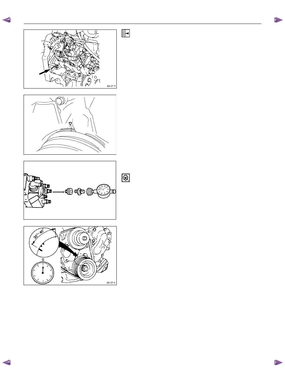
INJECTION TIMING ADJUSTMENT
(4JA1T(L) only)
1. Check that the notched line on the injection pump
flange is aligned with the front plate or the timing gear
case notched line.
2. Bring the piston in the No. 1 cylinder to TDC on the
compression stroke by turning the crankshaft until the
crankshaft pulley TDC line is aligned with the timing
mark.
Note:
Check for play in the No. 1 intake and exhaust valve
push rods.
If the No. 1 cylinder intake and exhaust valve push
rods have play, the No. 1 piston is at TDC on the
compression stroke.
RTW46ASH000601
3. Disconnect the injection pipe from the injection pump
4. Remove one bolt from the distributor head.
5. Install the adapter set, togather with static timing
gauge.
The probe of the gauge should be depressed inward
approximately 2 mm (0.079 in).
Static Timing Gauge: 5-8840-0145-0 (J-28827)
Adapter Set: Static Timing Gauge: 5-8840-2834-0
RTW36ASH002101
6. Rotate the crankshaft to bring the piston in the No. 1
cylinder to a point 30 - 40
° BTDC.
7. Set the timing gauge needle to zero.
8. Move the crankshaft pulley slightly in both directions to
check that the gauge indication is stable.
6A – 34 ENGINE MECHANICAL
RTW46ASH000701
9. Turn the crankshaft clockwise and read the gauge
indication when the crankshaft pulley timing mark (8
°)
is aligned with the pointer.
Injection Timing : BTDC 8
° ± 2°
Standard Reading
mm (in)
0.5 (0.02)
If the injection timing is outside the specified range,
continue with the following steps.
10. Loosen the injection pump fixing nuts and bracket
bolts.
11. Adjust the injection pump setting angle.
When large than standard
value
When smaller than standard
value
R A
A: Move the injection pump toward the engine.
R: Move the injection pump away from the engine.
12. Install the distributor head bolt.
Distributor head bolt torque N·m (kg·m /lb·ft)
29 (3.0/22)
ENGINE CONTROL (4JA1T(L) only)
Idling Speed Adjustment
1. Set the vehicle parking brake and chock the drive
wheels.
2. Place the transmission in neutral.
3. Start the engine and allow it to idle until the coolant
temperature reaches 70 - 80
°C (158 - 176°F).
4. Disconnect the engine control cable from the control
lever.
5. Set a tachometer to the engine.
6. Check the engine idling speed.
If the engine idling speed is outside the specified
range, it must be adjusted.
Engine Idling Speed : 730
± 25 rpm
Нет комментариевНе стесняйтесь поделиться с нами вашим ценным мнением.
Текст