Isuzu KB P190. Manual — part 367
6A-108 ENGINE MECHANICAL (4JK1/4JJ1)
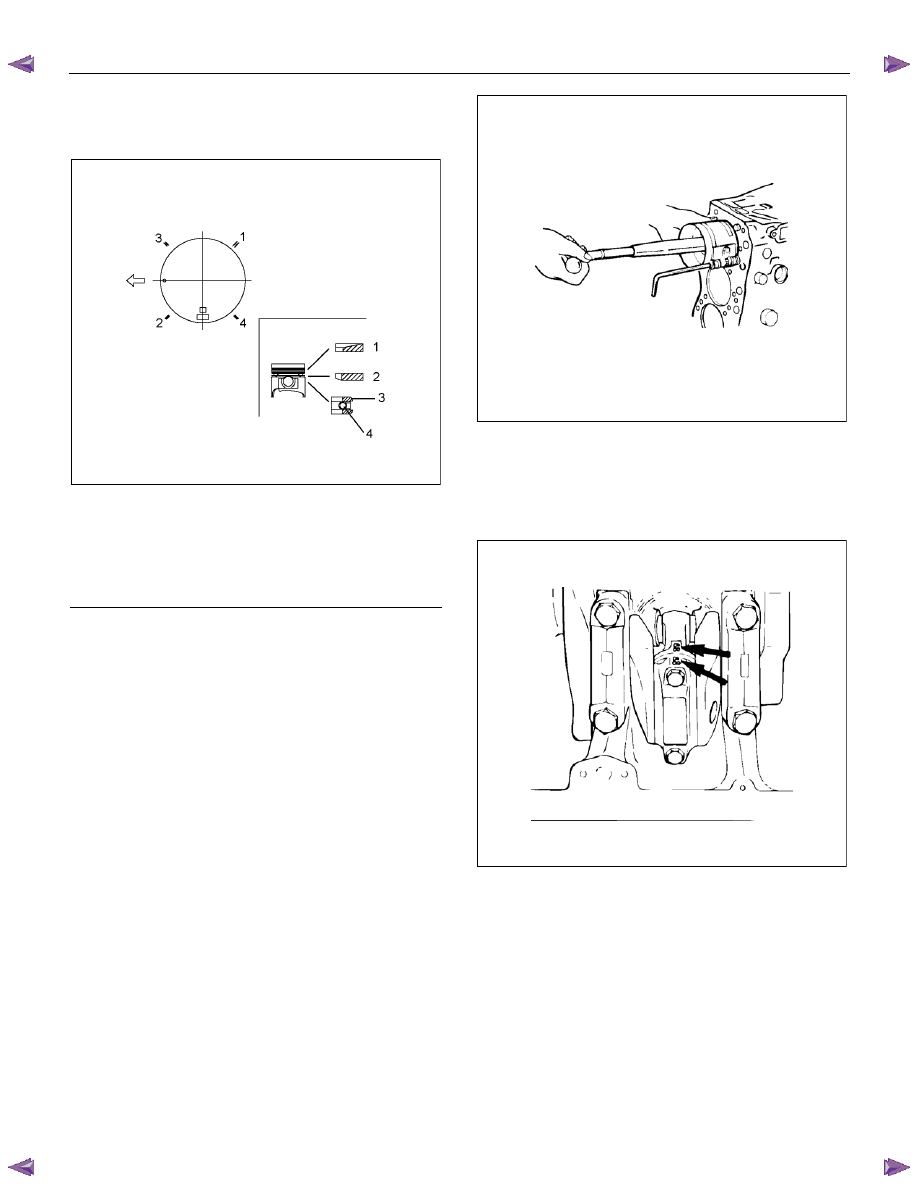
• Insert the expander coil into the oil ring groove
so that there is no gap on either side of the
expander coil before installing the oil ring.
RTW56ASH023201
Legend
1. Compression Ring 1st
2. Compression Ring 2nd
3. Oil
Ring
4. Expander
Installation
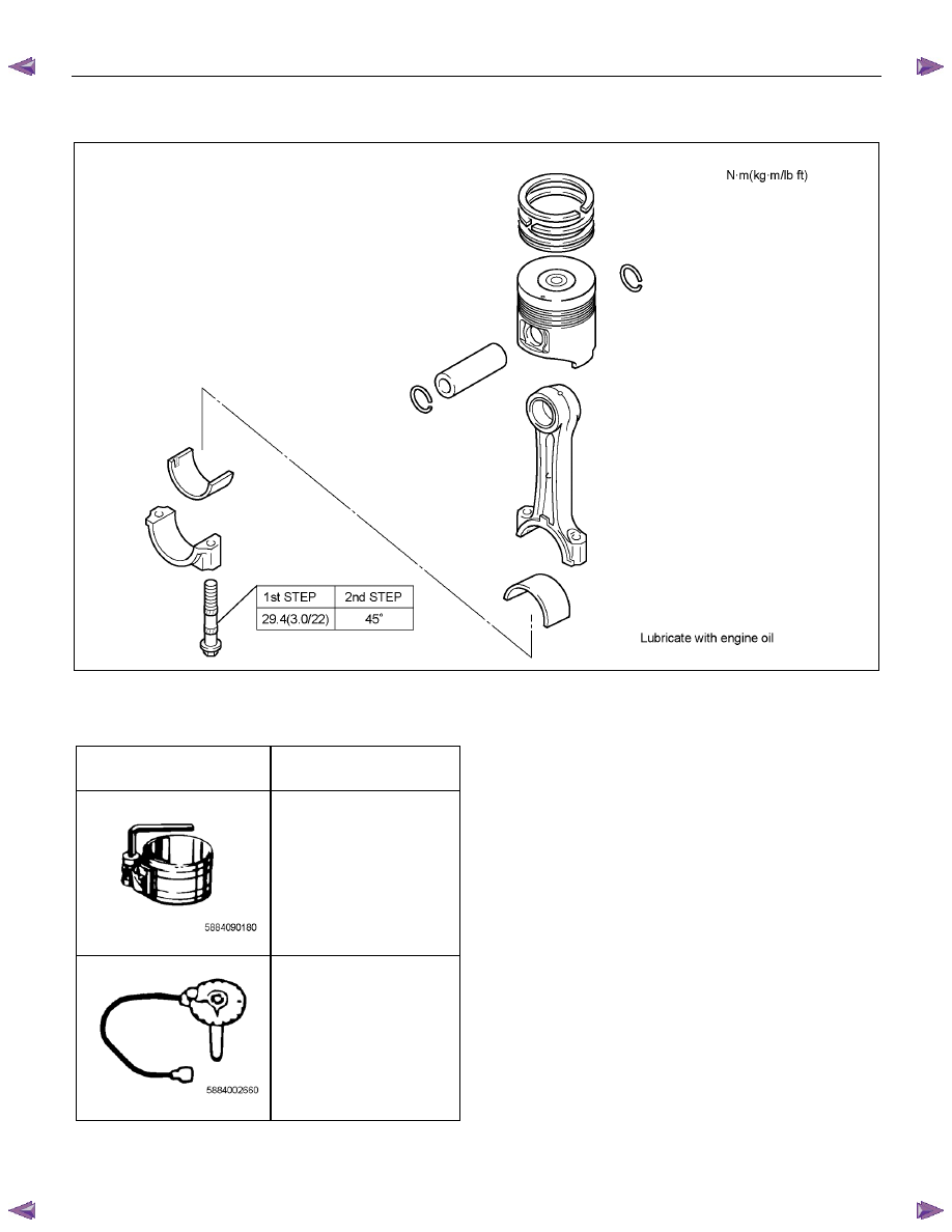
1. Install the connecting rod bearing.
• Install the bearing on the connecting rod, and
apply engine oil on the bearing.
2. Install the piston and connecting rod assembly.
• Apply enough engine oil on the piston ring, ring
groove and piston side surface.
• With the piston front mark cut facing forward,
use the piston ring compressor to insert the
piston in the cylinder block.
Note:
• Be sure not to make the connecting rod touch
the oil jet when pushing in the piston.
• Be sure not to harm the inside of the cylinder
block when pushing in the piston.
Special
tool
Piston ring compressor: 5-8840-9018-0
015LX096
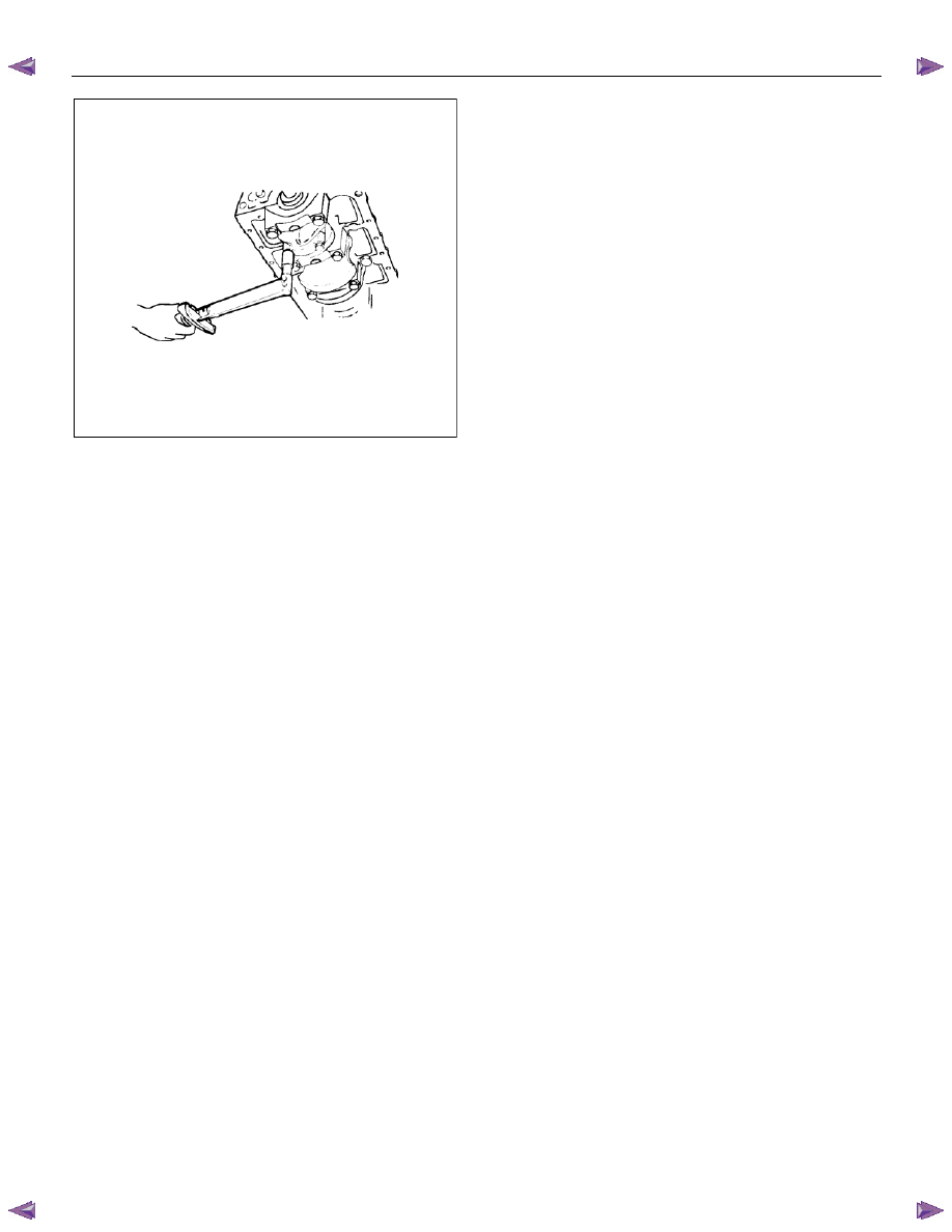
3. Install the connecting rod cap.
• Install the bearing on the connecting rod cap
and apply engine oil.
• Install the cap, matching the numbers (1, 2, 3,
and 4) of the caps and connecting rods.
015R100007
• Apply engine oil disulfide on the screw part and
the setting face of the tightening bolt and
tighten it with the designated torque.
Tightening torque:
1st step = 29 N
⋅⋅⋅⋅m (3.0 kg⋅⋅⋅⋅m / 22 lb ft)
2nd step = 45° (degrees)
Special
tool
Angle gauge: 5-8840-0266-0
Note:
Make sure that the crankshaft smoothly rotates.
ENGINE MECHANICAL (4JK1/4JJ1) 6A-109
015LX130
4. Install the oil pan.
Refer to “Oil Pan”.
5. Install the gear case assembly.
Refer to “Gear Case Assembly”.
6. Install the cylinder head.
Refer to “Cylinder Head”.
7. Install the camshaft assembly.
Refer to “Camshaft Assembly”.
8. Install the cylinder head cover.
Refer to “Cylinder Head Cover”.
6A-110 ENGINE MECHANICAL (4JK1/4JJ1)
Torque Specifications
RTW56AMF001801
Special Tools
ILLUSTRATION
PART NO.
PART NAME
5-8840-9018-0
Piston ring compressor
5-8840-0266-0
Angle gauge

ENGINE MECHANICAL (4JK1/4JJ1) 6A-111
Flywheel
Components
RTW56ALF001701
Legend
1. Flywheel Assembly and Pilot Bearing
2. Driven
Plate
3. Pressure Plate Assembly
4.
Release
Bearing
5. Shift
Fork
6. Transmission
Assembly
Removal
1. Remove the transmission assembly.
Refer to "transmission assembly removal and
installation".
2. Remove the clutch pressure plate.
• Remove the pressure plate installation bolts in
the order shown in the drawing.
• Remove the pressure plate from the flywheel.
Нет комментариевНе стесняйтесь поделиться с нами вашим ценным мнением.
Текст