Isuzu KB P190. Manual — part 366
6A-104 ENGINE MECHANICAL (4JK1/4JJ1)
4JK1
RTW56ASH025701
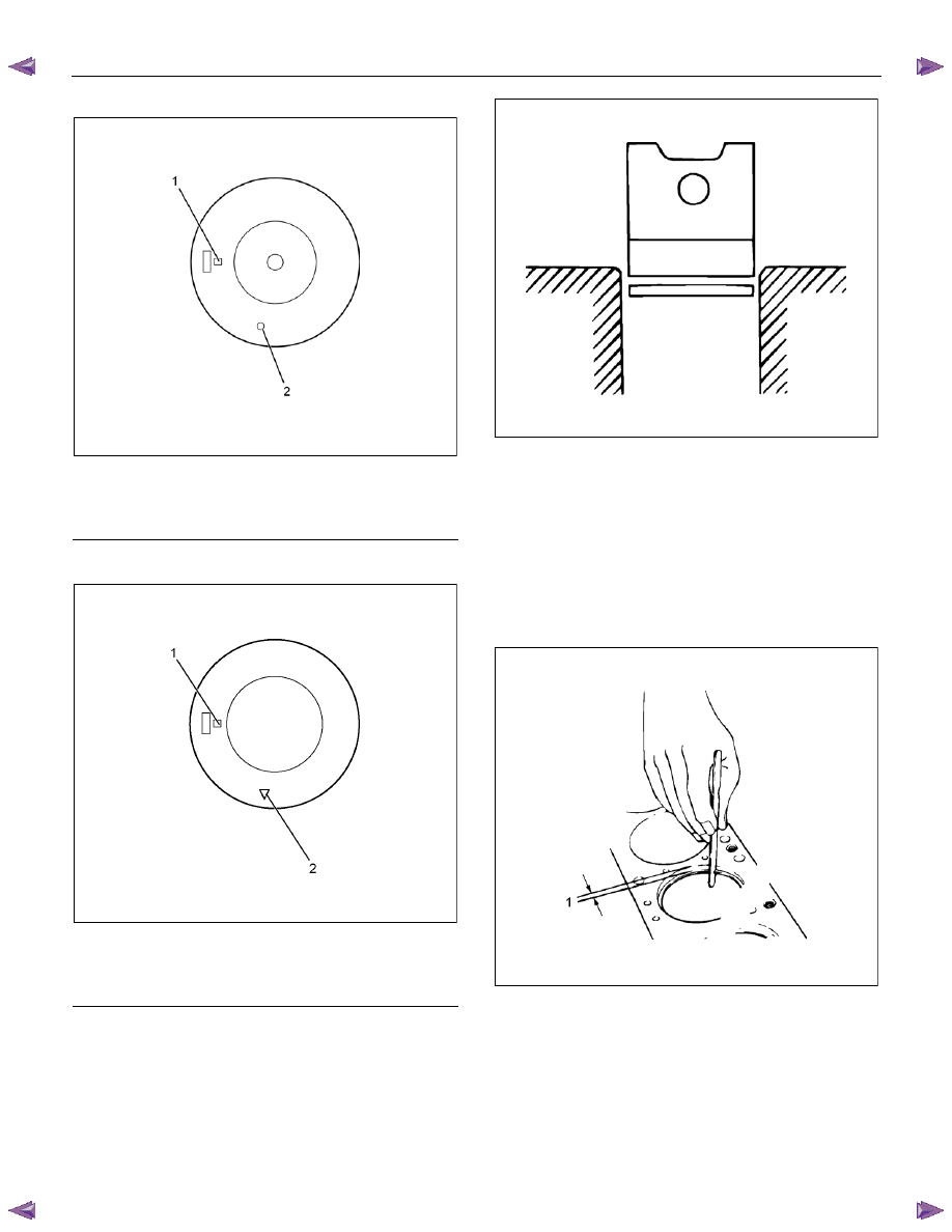
Legend
1. Grade
2. Front Mark Cut
4JJ1
LNW76ASH001401
Legend
1. Grade
2. Front Mark Cut
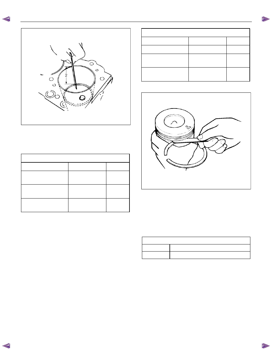
8. Inspect the piston ring.
• Insert the piston ring horizontally (in the position
it would assume if it were installed to the
piston) into the cylinder block.
LNW21BSH009301
• Push the piston ring into the cylinder bore until
it reaches the measuring point 1 or 2 where the
cylinder block bore is the smallest.
Do not allow the piston ring to slant to one side
or the other. It must be perfectly horizontal.
Measuring Point 1
10 mm (0.4 in)
or
Measuring Point 2
120 mm (4.7 in).
LNW61ASH004401
ENGINE MECHANICAL (4JK1/4JJ1) 6A-105
LNW61ASH004501
• Use a thickness gauge to measure the piston
ring gap.
If the measured value exceeds the specified
limit, the piston ring must be replaced.
Piston ring gap
mm (in)
Standard
Limit
1st compression ring
0.3 - 0.5
(0.0118 - 0.0197)
1.50
(0.059)
2nd compression ring
0.3 - 0.5
(0.0118 - 0.0197)
1.50
(0.059)
Oil ring
0.25 - 0.45
(0.0098- 0.0177)
1.50
(0.059)
Measure the clearance between the piston ring
groove and the piston.
• Remove carbon in the piston ring groove.
• Put the piston ring in the piston ring groove, use
a thickness gauge to measure the gap between
them.
• If the clearance between the piston ring groove
and the piston exceeds the limit, replace the
piston and the piston ring.
Piston ring and piston ring groove clearance mm (in)
Standard
Limit
1st compression ring
—
∗
—
∗
2nd compression ring
0.05 - 0.09
(0.0020 - 0.0035)
1.50
(0.059)
Oil ring
0.03 - 0.07
(0.0012- 0.0028)
1.50
(0.059)
∗
Measurement is impossible
LNW21BSH009501
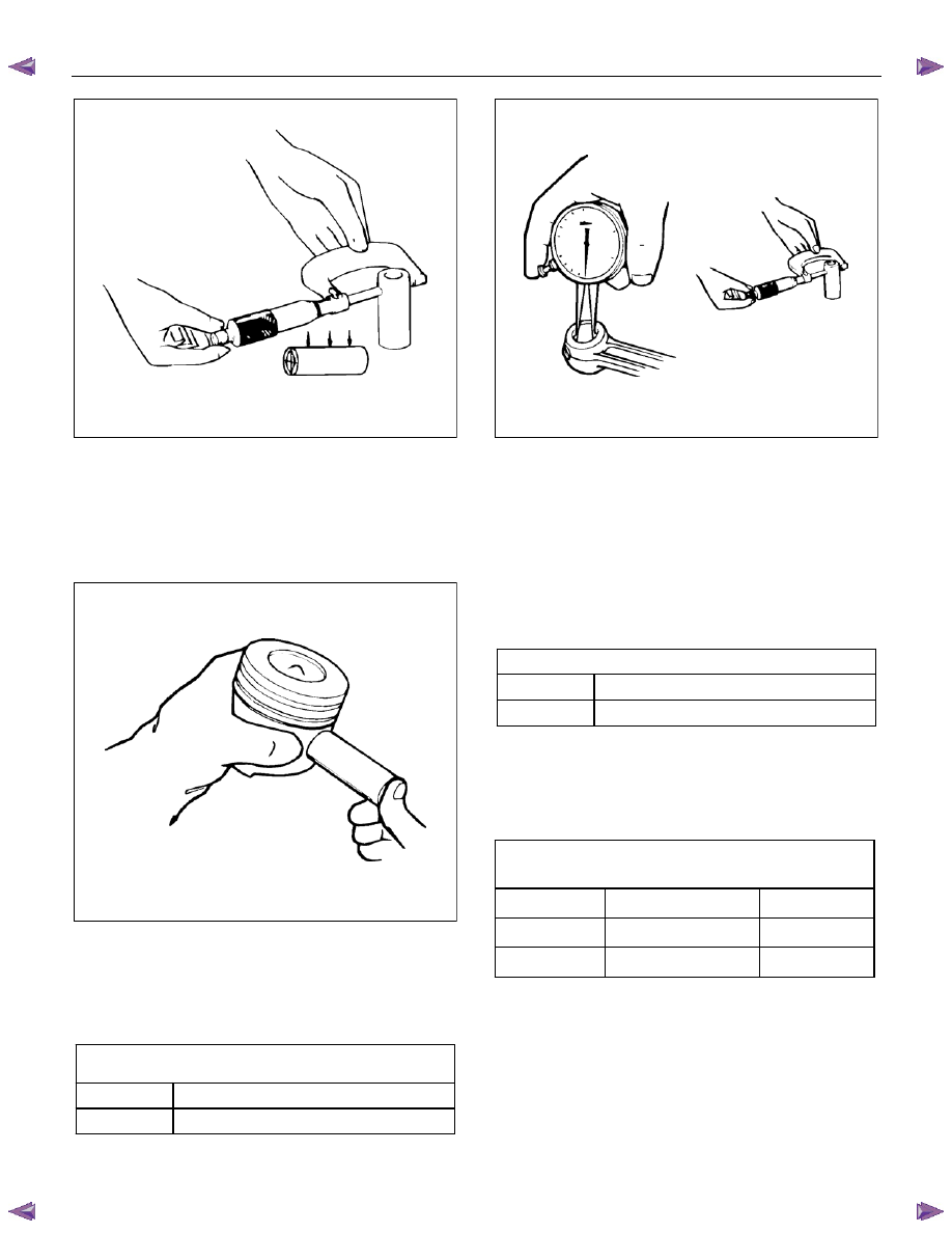
9. Inspect the piston pin.
• Visually inspect the piston pin for cracks,
scratches and other damage, and replace it if
necessary.
• Use a micrometer to measure the outer
diameter of the piston pin. If the measured
value exceeds the limit, replace the piston pin.
Piston pin outer diameter
mm (in)
Standard
33.995 – 34.000 (1.33838 – 1.33858)
Limit 33.970
(1.33740)
6A-106 ENGINE MECHANICAL (4JK1/4JJ1)
LNW21BSH009601
• Inspect to make sure that there is a resistance
to the extent which the piston can push the
piston pin lightly in normal temperatures.
• If it feels a large looseness or instability in
normal temperatures, replace the piston or
piston pin.
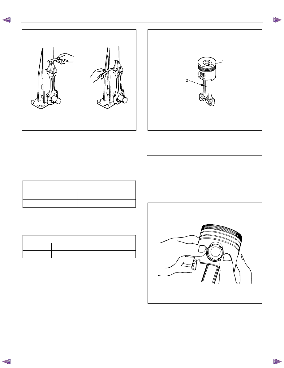
LNW21BSH009701
• Measure the bush of the small edge of the
connecting rod. If the clearance of the bush inner
diameter and the pin diameter exceeds the limit,
replace the bush or connecting rod assembly, and
the pin.
Piston pin and connecting rod small end bushing
clearance mm
(in)
Standard
0.008 - 0.020 (0.0003 - 0.0008)
Limit 0.05
(0.0020)
LNW21BSH009801
10.
Measure the clearance between the piston and
the piston pin.
• Apply engine oil on the piston pin. Use your
finger to push it in the piston hole and rotate it.
If the pin smoothly rotates without instability,
the clearance is normal. If there is instability,
measure the clearance. If the clearance
exceeds the limit, replace the piston and the
piston pin.
Piston pin and piston pin hole clearance
mm (in)
Standard
0.004 - 0.017 (0.0002 - 0.0007)
Limit 0.04
(0.0016)
11. Measure the connecting rod alignment.
• Use a connecting rod aligner to measure the
torsion and parallel level of the big end hole
and the small end hole. If the measured value
exceeds the limit, replace it.
Connecting rod alignment
(par length of 100 mm (3.94 in))
mm (in)
Standard
Limit
Distortion
0.08 (0.003) or less
0.20 (0.008)
Parallelism
0.05 (0.002) or less
1.50 (0.060)
ENGINE MECHANICAL (4JK1/4JJ1) 6A-107
LNW21BSH010401
12. Measure the bearing oil clearance.
• Install the bearing to the connecting rod big
end.
• Tighten the bearing cap to the two step of
angular tightening method.
• Use an inside dial indicator to measure the
connecting rod bearing inside diameter.
Connecting rod bearing cap bolt torque:
N
⋅m (kg⋅m / lb ft)
1st step
29.4 (3.0 / 22)
2nd step
45 deg
If the clearance between the measured bearing
inside diameter and the crankpin exceeds the
specified limit, the bearing and/or the crankshaft
must be replaced.
Crankpin and bearing clearance
mm (in)
Standard
0.029 - 0.083 (0.0011 - 0.0033)
Limit 0.10
(0.0039)
Reassembly
1. Install the piston.
2. Install the connecting rod.
• Install it so that the front mark of the head of
the piston, and the connecting rod forging mark
(projecting) on the connecting rod, both face in
the same direction.
• Install the snap ring of one side.
LNW46ASH004601
Legend
1. Front
Mark
2. Forging Mark (Projecting)
4. Apply enough engine oil on the piston pin, push it
in the piston and the connecting rod small edge.
5. Use snap ring pliers to install the snap ring.
Note:
Make sure that the snap ring is installed in the ring
groove properly. Make sure that the connecting rod
moves smoothly.
015R100001
6. Use ring pliers to install the piston ring.
• Install the piston rings in the order shown in the
illustration.
• Install 2nd and 1st compression rings in this
order so that the marks “2N” and “N” face
upward.
Нет комментариевНе стесняйтесь поделиться с нами вашим ценным мнением.
Текст