Isuzu KB P190. Manual — part 365
6A-100 ENGINE MECHANICAL (4JK1/4JJ1)
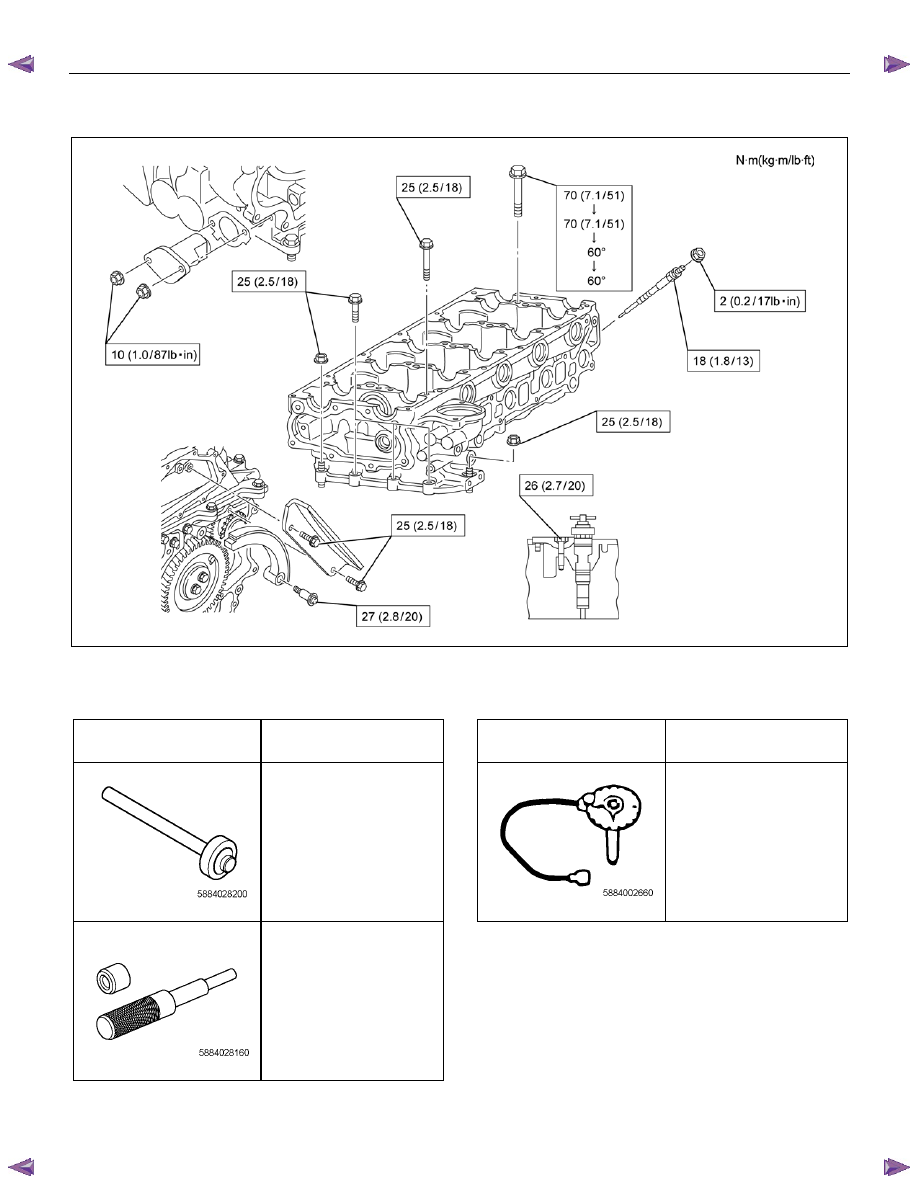
Torque Specifications
RTW76AMF000201
Special Tools
ILLUSTRATION
PART NO.
PART NAME
ILLUSTRATION
PART NO.
PART NAME
5-8840-2820-0
Injection pipe oil seal
installer
5-8840-0266-0
Angle gauge
5-8840-2816-0
Valve guide remover and
installer
ENGINE MECHANICAL (4JK1/4JJ1) 6A-101
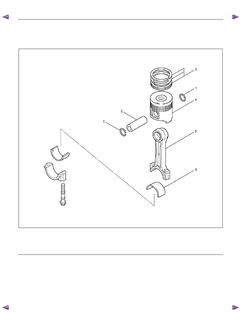
Piston and Connecting Rod
Components
RTWA56ALF001601
Legend
1. Piston Pin Snap Ring
2. Piston
Pin
3. Piston
Ring
4.
Piston
5. Connecting
Rod
6. Bearing
Removal
1. Demount the engine assembly.
Refer to “Engine Assembly”.
2. Remove the cylinder head cover.
Refer to “Cylinder Head Cover”.
3. Remove the camshaft assembly.
Refer to “Camshaft Assembly”.
4. Remove the cylinder head.
Refer to “Cylinder Head”.
5. Remove the gear case assembly.
Refer to “Gear Case Assembly”.
6. Remove the oil pan.
Refer to “Oil Pan” .
7. Remove the connecting rod cap.
6A-102 ENGINE MECHANICAL (4JK1/4JJ1)
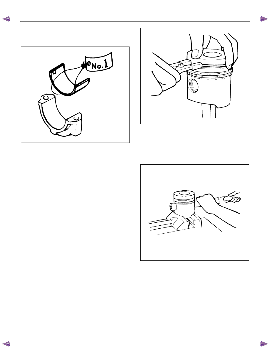
Note:
Sort the removed bearings according to cylinders by
using tags.
LNW21BSH004901
8. Remove the piston and connecting rod.
• Remove carbon on the upper side of the
cylinder block with a scraper.
• Pull out the piston and connecting rod towards
the cylinder head.
Note:
Be sure not to damage the oil jet and cylinder block
when pushing out the connecting rod.
9. Remove the connecting rod bearing.
Note:
Sort the bearings in the order of cylinders when reusing
them so that they are not confused with the bearings of
other cylinders.
Disassembly
1. Remove the piston ring.
• Use ring pliers to remove the piston ring.
Note:
Sort the piston rings in the same order as the cylinders
when reusing them so that they are not confused with
the pistons and piston rings of other cylinders.
LNW21BSH005101
2. Remove the snap ring.
3. Remove the piston pin.
Note:
Sort the disassembled piston pins,
pistons and
connecting rods together in the same order as the
cylinders.
LNW21BSH005201
4. Remove the connecting rods from the piston.
5. Clean the piston.
• Carefully clean carbon that is adhered to the
head of the piston and the groove of the piston
ring.
Note:
Do not use a wire brush to clean the piston because it
scratches the piston.
Visually inspect the piston for cracks, burns and other
excessive wear, and replace it if there is any
abnormality.
ENGINE MECHANICAL (4JK1/4JJ1) 6A-103
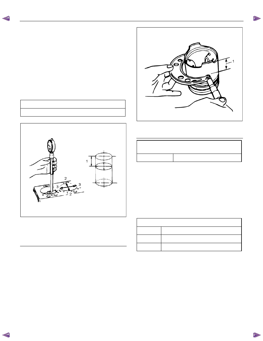
6. Measure the gap between the piston and the inner
diameter of the cylinder block.
Inner diameter of the cylinder block.
• Use a cylinder bore dial indicator to measure
the cylinder block inner diameter both in the
thrust and radial directions in the designated
position.
• Measurement position (from the upper surface
of the cylinder block) 20 mm (0.79 in)
• Measure the cylinder block inner diameter
based on the average value of the actual
measurement values on 6 positions.
Cylinder block inner diameter
mm (in)
95.421 – 95.450 (3.75673 – 3.75787)
LNW61ASH006401
Legend
1. 20 mm (0.79 in)
2. Radial
3. Thrust
Piston outside diameter
• Use a micrometer to measure the outside
diameter of the piston in the right angle to the
piston pin in the designated position.
• Measurement position (from the bottom surface
of the piston) 11.00 mm (0.43 in).
RTW56ASH023101
Legend
1. 11 mm (0.43 in)
Gap between the piston and the inner
diameter of the cylinder block
mm (in)
Standard
0.082 – 0.100 (0.0032 – 0.0039)
NOTE:
If the gap exceeds the standard value, replace the
piston or rebore the cylinder block.
7. Piston replacement
• The head of piston has a marking of grade A, B
or C.
• Refer to “Cylinder Block” if over size piston is
installed.
Piston Grade (Service Part)
mm (in)
A
95.330 – 95.339 (3.75314 – 3.75350)
B
95.340 – 95.349 (3.75354 – 3.75389)
C
95.350 – 95.359 (3.75393 – 3.75428)
Нет комментариевНе стесняйтесь поделиться с нами вашим ценным мнением.
Текст