Isuzu KB P190. Manual — part 665
Engine Mechanical – V6
Page 6A1–181
3.23 Engine Mounts and Brackets
Remove
1
Remove the exhaust manifold assembly from the side of the engine where the engine mount is to be removed,
refer to 3.11
Exhaust Manifold Assembly.
2
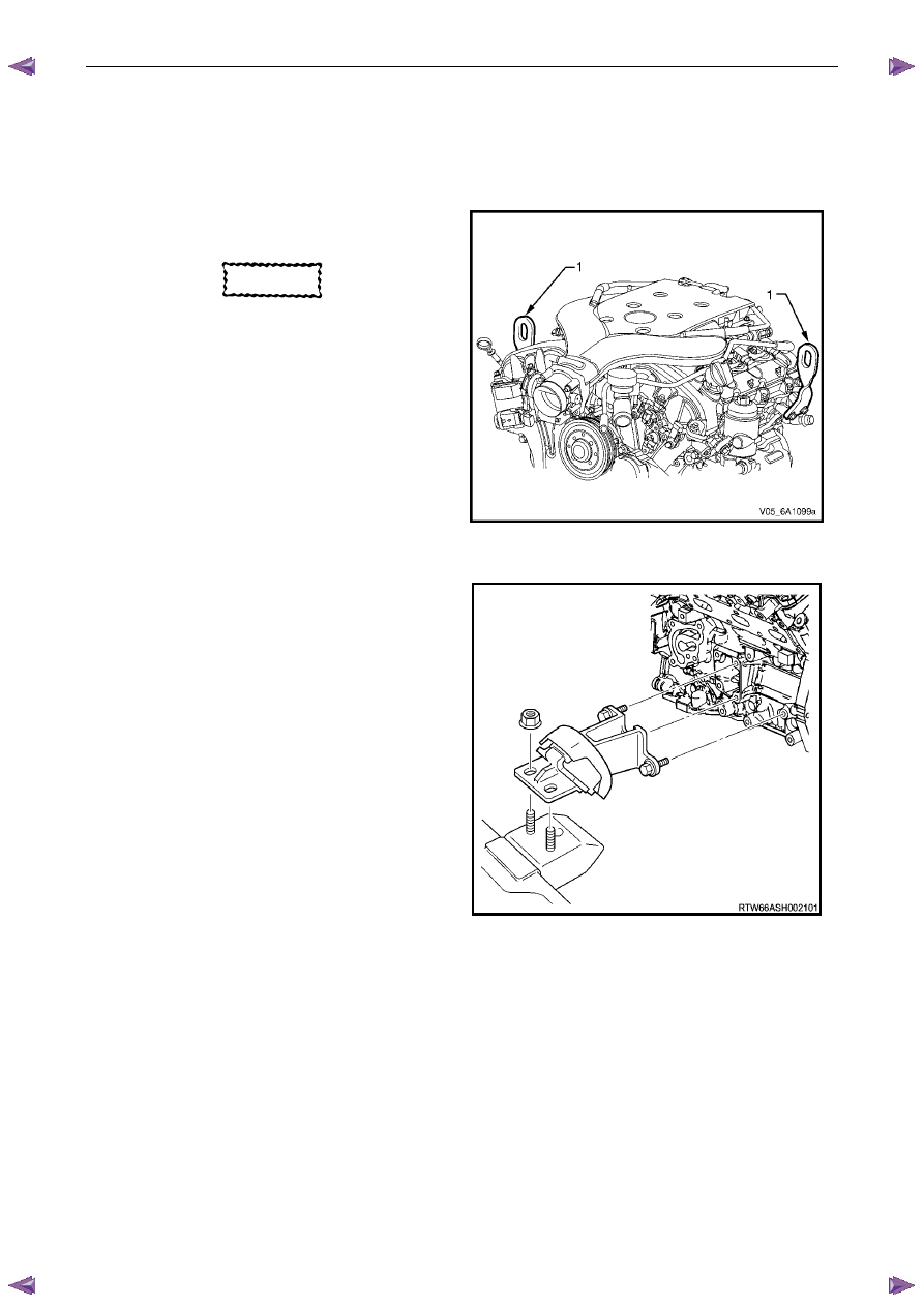
Fit the engine lift brackets, Tool No. EN-46114 (1) to
the cylinder heads.
CAUTION
Only lift the engine far enough to take the
weight off the engine mount, or damage to
the mount and lifting equipment failure may
occur.
3
Using an engine lifting crane, raise the side of the
engine where the mount is to be removed enough to
remove the weight from the engine mounts, and
create a slight tension in the lifting equipment.
Figure 6A1 – 314
4
Remove the left-hand or right-hand side engine
mount and bracket as required.
Figure 6A1 – 315
Engine Mechanical – V6
Page 6A1–182
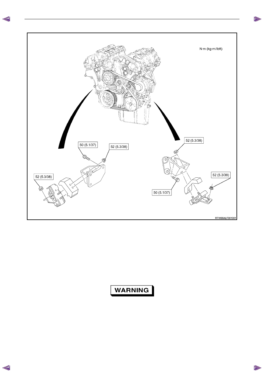
Engine Mount Location
Figure 6A1 – 316
Inspect
N O T E
Although the following procedure provides
information regarding on-vehicle engine mount
inspections, it is preferable to inspect the engine
mounts once removed from the vehicle.
1
Fit the engine lift brackets, Tool No. EN-4611 to the cylinder heads.
Only lift the engine enough to take the weight
off the engine mounts, or damage to the
mounts and lifting equipment failure may
occur.
2
Using a commercially available engine lifting crane, have an assistant raise the engine far enough to remove the
weight on the engine mounts and create a slight tension in the rubber.
3
Observe the engine mount while raising the engine.
4
Replace the engine mount if any of the following conditions are found:

Engine Mechanical – V6
Page 6A1–183
•
The hard rubber surface is covered with heat check cracks,
•
The rubber is split through the centre of the engine mount, or
•
The rubber is separated from the metal plate portion of the engine mount.
5
Remove the engine lift brackets, Tool No. EN-46114 from the engine.
Reinstall
The reinstallation procedure for the engine mounts is the reverse of the removal procedure, noting the following:
Ensure all fasteners are tightened to the correct torque specification.
Engine mount bracket to
cylinder block attaching bolt
torque specification
. . . . . . . . . . . . . . . . 43.0 – 57.0 Nm
Engine mount to bracket attaching nut
torque specification
. . . . . . . . . . . . . . . . 70.0 – 90.0 Nm
Engine mount to frame attaching nut
torque specification
. . . . . . . . . . . . . . . . 44.0 – 60.0 Nm
Engine Mechanical – V6
Page 6A1–184
4
Major Service Operations
A T T E N T I O N
The V6 engine is a combination of numerous components, containing machined, honed, polished and lapped
surfaces manufactured on the latest, high technology production equipment. Many of the components
contain tolerances measured in thousandths of a millimetre. Consequently, when any engine component is to
be serviced, care and cleanliness are extremely important.
Prior to re-assembly of the V6 engine, all components must be cleaned and inspected in accordance with the
relevant procedures throughout this section, and replaced or repaired where required.
In addition to cleaning and inspecting components, a liberal coating of engine oil should be applied to friction
surfaces during assembly to protect and lubricate the surfaces on initial operation.
When performing any service operation contained in this Section, it should be understood that correct
cleaning and protection of machined surfaces and friction areas is part of the repair procedure. This is
considered standard workshop practice, even if not specifically stated. Torque values must be used as
specified during reassembly to ensure correct retention of all components.
Through out this section, fastener torque wrench specifications may be accompanied with the following
identification marks:
■
Fasteners must be replaced after loosening.
Fasteners either have micro encapsulated sealant applied or incorporate a mechanical thread lock and
should only be re-used once. If in doubt, replacement is recommended.
If one of these identification marks is present alongside a fastener torque wrench specification, the
recommendation regarding that fastener must be adhered to.
4.1 Engine
Removal
CAUTION
• Allow the engine to cool to at least 50°°°° C,
before attempting fastener removal.
• As aluminium has a greater rate of thermal
expansion than that of cast iron,
aluminium bolt hole threads will change
dimension to a larger extent than cast iron
bolt threads.
• If a bolt or other threaded component is
removed before the engine is allowed to
cool to at least 50
°°°° C, threads could be
pulled from the cylinder block or cylinder
head.
• Do not use impact tools to remove bolts
during engine disassembly. While this may
be common practice with cast iron engine
components, use of these tools is likely to
pull the aluminium threads in the cylinder
block or head of this engine.
Нет комментариевНе стесняйтесь поделиться с нами вашим ценным мнением.
Текст