Isuzu KB P190. Manual — part 906
Starting System – V6
Page 6D1-2–16
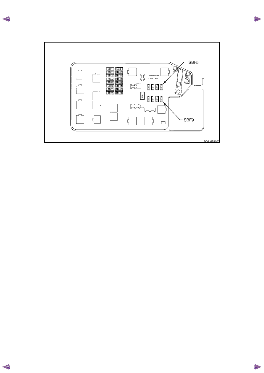
Engine Compartment Relay And Fuse Panel
Figure 6D1-2 – 4
1
Remove fuses SBF5 and SBF9 from the engine compartment fuse panel to disable the ignition and prevent the
engine from starting, refer to 8A Electrical Body and Chassis.
2
Chock the wheels.
3
For vehicles fitted with automatic transmission ensure the transmission is in P (park) or N (neutral) and the hand
brake is applied.
4
Ensure the engine is at room temperature or normal operating temperature and in good working order.
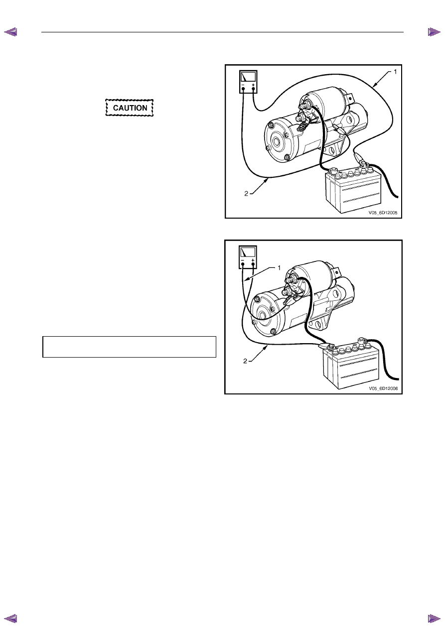
Bad Connection Test
A bad connection appears as a voltage reading when the multimeter leads are connected to two different positive (or
negative) connections.
1
Using a multimeter set to measure voltage, connect the multimeter’s positive lead to the positive battery post.
2
Connect the multimeter’s negative lead to the starter motor M terminal.
3
Record the voltage that displayed during cranking.
4
Repeat this with the multimeter’s negative lead connected to the solenoid switch connector P – 4 pin B
(circuit 1).
5
Also repeat this connecting the multimeter’s negative lead to the battery cable strands.
6
Restore all connections that show a significant resistance (voltage reading).
Starting System – V6
Page 6D1-2–17
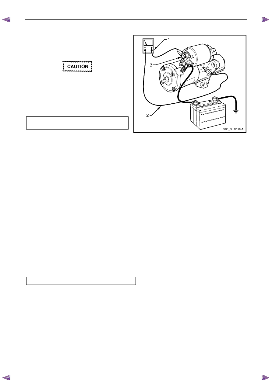
Starter Motor Ground Test
1
Using a multimeter set to measure voltage, connect
the multimeter’s positive lead (1) to the negative
battery post.
Connect the lead to the actual battery post
and not to the cable or connector.
2
Connect the multimeter’s negative lead (2) to the
starter motor housing.
3
Record the voltage that displayed during cranking.
4
Repeat this connecting the multimeter’s negative
lead to the battery cable strands.
5
Restore all ground connections that show a
significant resistance.
Figure 6D1-2 – 5
Switching Circuit Test
1
Using a multimeter set to measure voltage, connect
the multimeter’s negative lead (1) to the solenoid
switch connector P – 3 pin 1.
2
Connect the multimeter‘s positive lead (2) to the
positive battery post.
3
Crank the engine.
4
Record the voltage that displayed during cranking.
Maximum switching
circuit voltage difference. . . . . . . . . . .2.5 V
5
If the voltage is above the specification, test the
solenoid switching circuit to locate the cause of the
high resistance and restore the connection.
Figure 6D1-2 – 6
Starting System – V6
Page 6D1-2–18
Cranking Voltage Test
1
Using a multimeter set to measure voltage, attach
the multimeter’s negative lead to ground and the
multimeter’s positive lead to starter solenoid
connector P – 3 pin 1 (3) of the solenoid switch.
Do not crank the engine for more than
30 seconds at a time. Allow 2 minutes for
the starter motor to cool down between
tests.
3
Crank the engine.
4
Record the voltage that displayed during cranking.
Minimum cranking
voltage. . . . . . . . . . . . . . . . .9.0 V
5
Remove and repair or replace the starter motor
and solenoid switch if the voltage is below the
specifications and cranks poorly. Refer to 4
Major Service Operations.
Figure 6D1-2 – 7
Current Draw Test
1
Using a multimeter set to measure voltage, attach the multimeter’s positive lead to the positive battery post.
2
Attach the same multimeter’s negative lead to the negative battery post.
3
Using a multimeter set to measure current, attach the multimeter’s positive lead to the battery post.
4
Connect the negative lead of the multimeter set to measure current to a battery loading device, for example a
carbon pile.
5
Connect the free lead of the battery loading device to the negative battery terminal.
6
Set the battery loading device to maximum resistance (open).
7
Crank the engine.
8
Record the voltage that displayed during cranking.
9
With the ignition in the OFF position, adjust the battery loading device so the reading of the multimeter set to
measure voltage matches the reading recorded in the last step.
10
Record the current draw from the battery loading device.
11
Set the battery loading device back to ‘open’.
12
Check the current draw is within specifications.
Cranking current range . . . . . . . . 100 – 140 A
13
Remove and repair or replace the starter motor and solenoid switch if the current draw is outside the specification.
Refer to 4 Major Service Operations.
Starting System – V6
Page 6D1-2–19
4
Major Service Operations
Disconnection of the battery affects certain
vehicle electronic systems. Refer to 00
Warnings, Cautions and Notes before
disconnecting the battery.
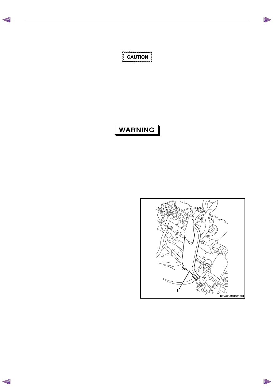
4.1
Starter Motor
Remove
The starter motor is in close proximity to the
left-hand side exhaust manifold and engine
pipe. Allow the engine to cool before
attempting to remove the starter motor.
1
Refer to 1.1 WARNING, CAUTION and NOTES in this Service Information before disconnecting the battery.
2
Disconnect the battery ground lead.
3
Raise the front of the vehicle. For jacking locations, refer to 0A General Information.
4
Put safety stands in place.
5
Fit the front lifting bracket: EN–46114 (1) to the
engine, then hook the chains from the engine hoist
onto the front lifting bracket.
Figure 6D1-2 – 8
Нет комментариевНе стесняйтесь поделиться с нами вашим ценным мнением.
Текст