Isuzu KB P190. Manual — part 907
Starting System – V6
Page 6D1-2–20
6
Fit the rear lifting brackets: EN–46114 (1) to the
engine, then hook the chains from the engine hoist
onto the rear lifting bracket.
7
Remove the oil level indicator tube, Refer to 6A1
Engine Mechanical – V6.
Figure 6D1-2 – 9
8
Remove the left hand side knock sensor (1) from the
engine block.
Figure 6D1-2 – 10
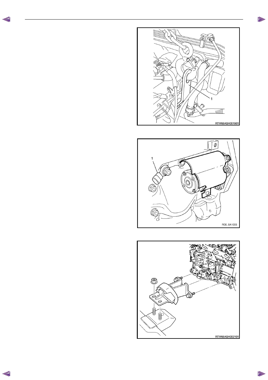
9
Remove the left hand side engine mount, then using
the engine hoist raise the engine to give sufficient
clearance to remove the starter motor.
Figure 6D1-2 – 11
Starting System – V6
Page 6D1-2–21
10
Unclip the oil level sensor harness from the heat shield
(1).
11
Remove the heat shield attaching screw (2).
12
Remove the lower starter motor attaching bolt (3).
13
Remove the heat shield.
14
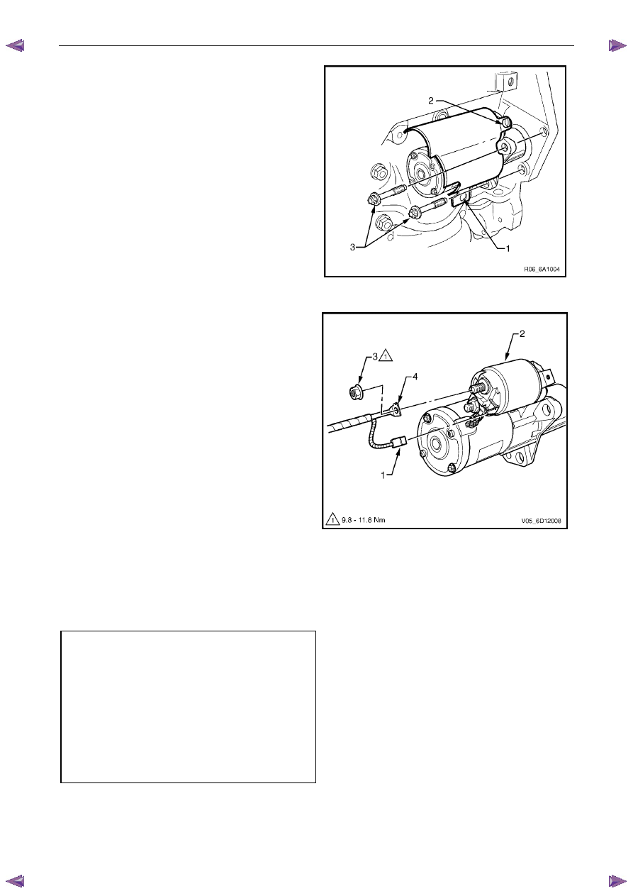
Remove the upper starter motor retaining bolt (3).
15
Remove the starter motor from the engine block and
lower the starter motor as far as possible to gain
access to the wiring harness connections.
Figure 6D1-2 – 12
16
Remove the wiring harness connector P – 3 (1) from
the solenoid switch (2).
17
Remove the flange nut (3) and battery connector P – 4
(4) from the solenoid switch.
18
Remove the starter motor from the vehicle.
Figure 6D1-2 – 13
Reinstall
Reinstallation of the starter motor is the reverse of the removal procedure noting the following:
1
Tighten all fasteners to the correct torque specification.
Solenoid switch connector P – 4 nut (B+)
torque specification . . . . . . . . . . . 10.0 Nm
Starter motor heat shield lower bolts
torque specification . . . . . . . . . . . 23.0 Nm
Starter motor heat shield upper screw
torque specification . . . . . . . . . .3.0 – 5.0 Nm
Starter motor mounting bolt
torque specification . . . . . . . . . . . 45.0 Nm
Knock sensor bolt
torque specification . . . . . . . . . . . 23.0 Nm
2
Check the starter motor operates correctly.
Starting System – V6
Page 6D1-2–22
4.3
Starter Motor Bench Tests
Preliminary Checks
1
Check the drive assembly is fully retracted.
2
Check the drive assembly pinion turns freely on the planetary drive shaft.
3
Perform the No Load Test (as outlined in this Section) if the drive assembly is not fully retracted.
4
Disassemble and service the starter motor if it fails the No Load test, refer to 4.4 Starter Motor Disassemble and
Reassemble in this Section.
Pull-in Test
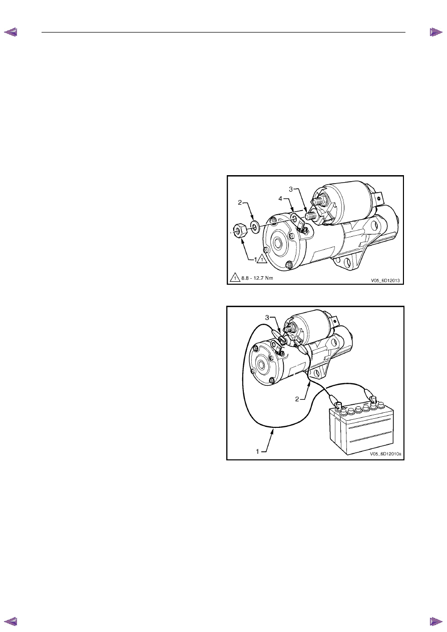
1
Clamp the starter motor, by the mounting lug in the
drive-end housing, in a vice with soft jaws.
2
Remove the nut (1) and washer (2) from the
solenoid switch M terminal (3).
3
Remove the braided cable (4) from the solenoid
switch M terminal.
Figure 6D1-2 – 14
4
Connect the starter motor to an auxiliary battery, as
follows:
a
Connect the test lead (1) between the battery
negative post to the solenoid switch M terminal
(3).
b
Connect the test lead (2) battery positive post.
5
Momentarily hold the free end of test lead (2) to
solenoid switch terminal P – 3.
6
Check the solenoid switch activates and the drive
assembly moves outward.
7
Disassemble and service the starter motor if the
solenoid switch activates but the drive assembly
does not move, refer to 4.4
Starter Motor
Disassemble and Reassemble in this Section.
8
Replace the solenoid switch if it does not activate
(there is no sound or movement).
Figure 6D1-2 – 15
Starting System – V6
Page 6D1-2–23
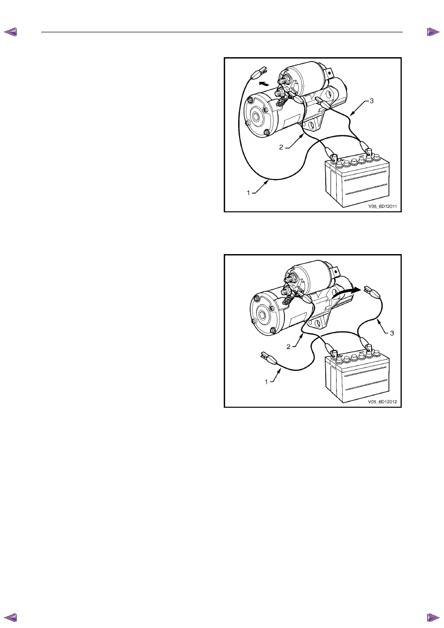
Hold-in Test
1
Connect the starter motor to an auxiliary battery, as
follows:
a
Connect the test lead (1) between the battery
negative post to the solenoid switch M
terminal.
b
Connect the test lead (2) from the battery
positive post to solenoid switch terminal
P – 3.
c
Connect the test lead (3) to the starter motor
casing.
2
Disconnect the test lead (1) from the M terminal of
the solenoid switch.
3
Check the drive assembly remains extended.
4
Replace the solenoid switch if the drive assembly
returns back into the starter motor.
Figure 6D1-2 – 16
Drive Assembly Return Test
1
Connect the starter motor to an auxiliary battery, as
follows:
a
Connect the test lead (1) between the battery
negative post to the solenoid switch M
terminal.
b
Connect the test lead (2) from the battery
positive post to solenoid switch terminal
P – 3.
c
Connect the test lead (3) to the starter motor
casing.
2
Disconnect the test lead (1) from the M terminal of
the solenoid switch.
3
Disconnect the negative lead (2) from the starter
motor casing.
4
Check the drive assembly returns back into the
starter motor.
5
Replace the solenoid switch if the drive assembly
does not retract.
Figure 6D1-2 – 17
Нет комментариевНе стесняйтесь поделиться с нами вашим ценным мнением.
Текст