Isuzu KB P190. Manual — part 773
Engine Mechanical – V6
Page 6A1–315
Page 6A1–315
20
Rotate the driver installation tool until the mark (1) on
the driver installation tool aligns with the top of the
drill bushing (2).
21
Inspect the insert for correct installation into the
tapped hole.
Figure 6A1 – 586
22
Remove the fixture plate bolts (1), bushing (2) and
fixture plate (3).
Figure 6A1 – 587
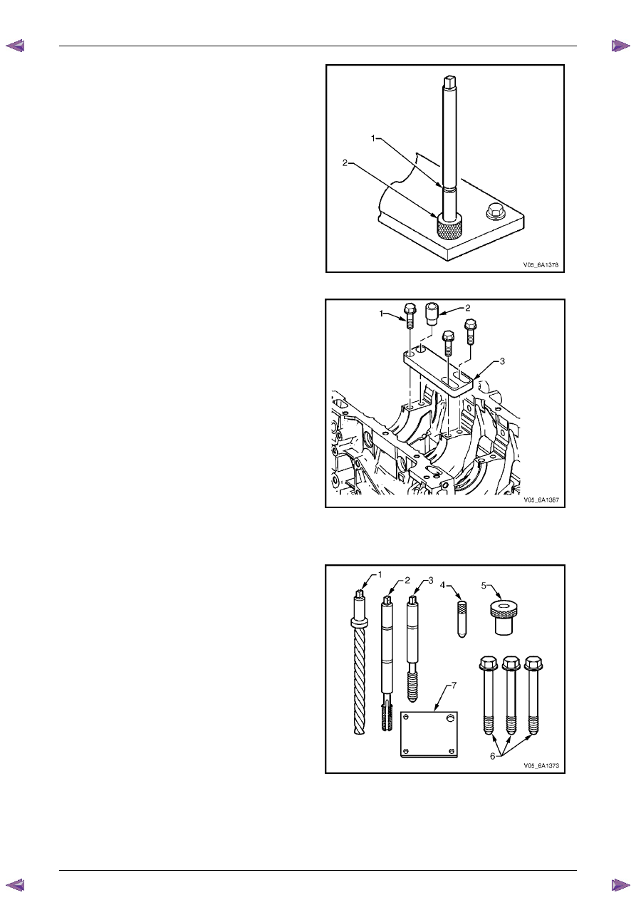
Cylinder Head Bolt Hole Thread Repair
The cylinder head bolt hole thread repair tools are in Tool
No. J 42385-2000 and J 42385-700 which consist of the
following:
•
Drill (1) J 42385-723
•
Tap (2) J 42385-724
•
Installation driver (3) J 42385-725
•
Alignment pin (4) J 42385-303
•
Bushing (5) J 42385-302
•
Bolts (6) J 42385-733
•
Fixture plate (7) J 42385-401
Figure 6A1 – 588
Engine Mechanical – V6
Page 6A1–316
Page 6A1–316
N O T E
• Ensure the fixture plate is installed during the
machining and installation processes of the
insert.
• The use of a cutting type fluid such as
WD 40® or equivalent is recommended when
performing the drilling, counter boring and
tapping procedures.
• When installed to the correct depth, the flange
of the insert will be seated against the counter
bore of the drilled/tapped hole.
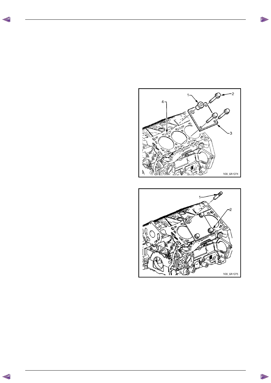
1
Position the fixture plate (3) with the bushing (1)
installed over the cylinder head bolt hole to be
repaired (4).
2
Loosely install the fixture plate bolts (2) into the
remaining cylinder head bolt holes.
Figure 6A1 – 589
3
Position the alignment pin (1) through the bushing
and into the cylinder head bolt hole.
4
With the alignment pin in the desired cylinder head
bolt hole, tighten the fixture retaining bolts (2).
5
Remove the alignment pin.
Figure 6A1 – 590
Engine Mechanical – V6
Page 6A1–317
Page 6A1–317
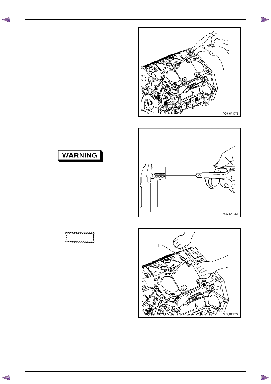
N O T E
During the drilling process, repeatedly remove
the drill and clean swarf from the hole and the
flutes of the drill.
6
Drill the hole until the stop collar contacts the top of
the drill bushing.
Figure 6A1 – 591
N O T E
All swarf must be removed from the drilled hole
prior to tapping.
Safety glasses must be worn when using
compressed air.
7
Using compressed air, clean out any swarf.
Figure 6A1 – 592
CAUTION
Do not remove the fixture plate during the
machining and installation processes of the
insert.
N O T E
• During the tapping process, repeatedly
remove the tap and clean swarf from the
hole and the flutes of the tap.
• Ensure the tap has created full threads at
least to the depth equal to the insert length.
8
Using a suitable tapping wrench, tap the threads of
the drilled hole by hand only.
Figure 6A1 – 593
Engine Mechanical – V6
Page 6A1–318
Page 6A1–318
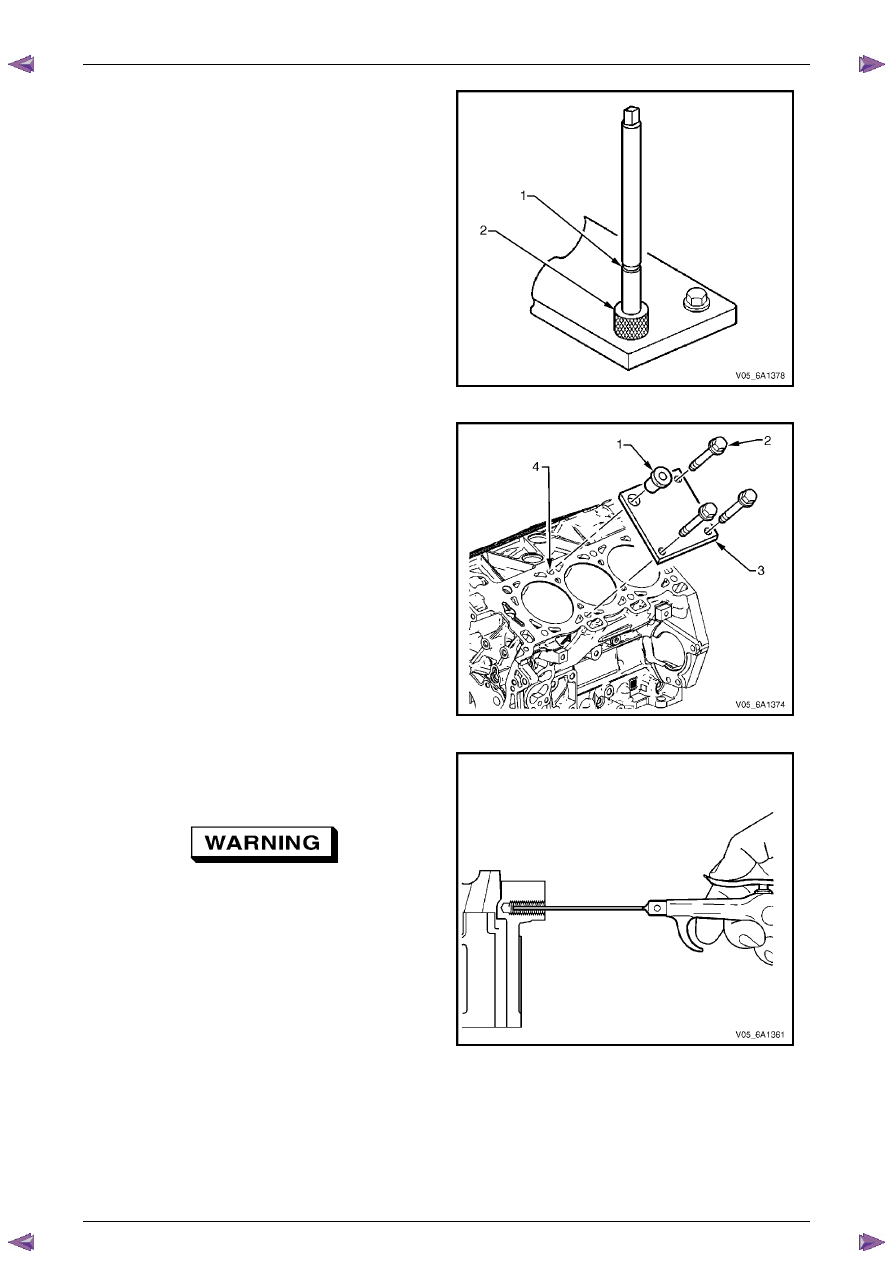
9
In order to tap the new threads for the insert to the
correct depth, rotate the tap into the cylinder head
bolt hole until the mark (1) on the tap aligns with the
top of the drill bushing (2).
Figure 6A1 – 594
N O T E
Remove the fixture plate prior to installing the
insert with the installer tool.
10
Remove the bushing (1) and fixture plate bolts (2)
from the cylinder block (4) and remove the fixture
plate (3).
Figure 6A1 – 595
N O T E
All swarf must be removed from the tapped hole
prior to insert installation.
Safety glasses must be worn when using
compressed air.
11
Using compressed air, clean out any swarf.
Figure 6A1 – 596
Нет комментариевНе стесняйтесь поделиться с нами вашим ценным мнением.
Текст