Isuzu KB P190. Manual — part 772
Engine Mechanical – V6
Page 6A1–311
Page 6A1–311
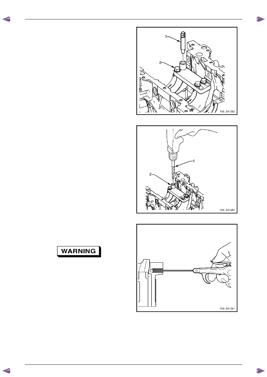
3
Position the alignment pin (1) through the bushing
and into the crankshaft main cap bolt hole.
4
With the alignment pin in the desired crankshaft main
cap bolt hole, tighten the fixture retaining bolts (2).
5
Remove the alignment pin.
Figure 6A1 – 574
6
Drill the crankshaft main bolt hole until the mark (1)
on the drill aligns with the top of the drill bushing (2).
N O T E
During the drilling process, repeatedly remove
the drill and clean the swarf from the hole and
the flutes of the drill.
Figure 6A1 – 575
N O T E
All swarf must be removed from the drilled hole
prior to tapping.
Safety glasses must be worn when using
compressed air.
7
Using compressed air, clean out any swarf.
Figure 6A1 – 576
Engine Mechanical – V6
Page 6A1–312
Page 6A1–312
N O T E
• During the tapping process, repeatedly
remove the tap and clean the swarf from the
hole and the flutes of the tap.
• Ensure the tap has created full threads at
least to the depth equal to the insert length.
CAUTION
Do not remove the fixture plate during the
machining and installation processes of the
insert.
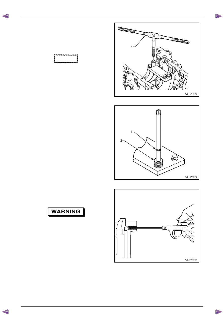
8
Using a suitable tapping wrench, tap the threads of
the drilled hole by hand only.
Figure 6A1 – 577
9
In order to tap the new threads for the insert to the
correct depth, rotate the tap into the crankshaft main
cap bolt hole until the mark (1) on the tap aligns with
the top of the drill bushing (2).
Figure 6A1 – 578
N O T E
All swarf must be removed from the tapped hole
prior to insert installation.
Safety glasses must be worn when using
compressed air.
10
Using compressed air, clean out any swarf.
Figure 6A1 – 579

Engine Mechanical – V6
Page 6A1–313
Page 6A1–313
11
Spray a commercially available thread cleaner into
the tapped hole.
Figure 6A1 – 580
N O T E
All swarf must be removed from the tapped hole
prior to insert installation.
Safety glasses must be worn when using
compressed air.
12
Using compressed air, clean out any swarf.
Figure 6A1 – 581
N O T E
• Do not remove the fixture plate, ensure the
fixture plate is installed during the
installation process of the insert.
• Do not allow oil or other foreign material to
contact the outside diameter (OD) of the
insert.
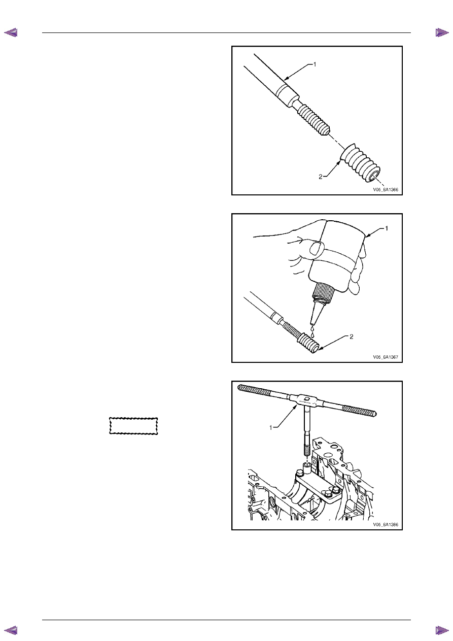
13
Lubricate the threads of the driver installation tool (2)
with the driver oil (1).
Figure 6A1 – 582
Engine Mechanical – V6
Page 6A1–314
Page 6A1–314
14
Install the insert (2) onto the driver installation tool (1).
Figure 6A1 – 583
15
Apply thread lock sealant (1) such as Loctite 277® or
equivalent to the insert OD threads (2).
Figure 6A1 – 584
16
Install the insert and installation driver (1) to the
tapped hole by hand only.
17
Start the insert into the threaded hole.
CAUTION
If the insert will not thread down until the
flange contacts the counter-bored surface,
remove the insert immediately with a screw
extracting tool and inspect the tapped hole
for any remaining swarf and/or incorrect
tapping.
18
Install the insert until the flange of the insert contacts
the counter-bored surface.
N O T E
The driver installation tool will tighten up before
cutting completely through the insert. This is
acceptable. The threads at the bottom of the
insert are being formed and the insert is
mechanically locking the insert into the base
material threads.
19
Continue to rotate the driver installation tool through
the insert.
Figure 6A1 – 585
Нет комментариевНе стесняйтесь поделиться с нами вашим ценным мнением.
Текст