Isuzu KB P190. Manual — part 740
Engine Mechanical – V6
Page 6A1–183
Page 6A1–183
Inspect
1
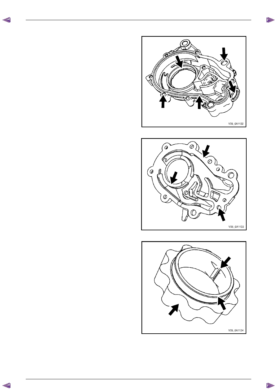
Inspect the oil pump housing for damage.
Figure 6A1 – 291
2
Inspect the oil pump cover for damage.
Figure 6A1 – 292
3
Inspect the inner drive gear for damage. If inner
surface damage is found, ensure the crankshaft is
also inspected.
Figure 6A1 – 293
Engine Mechanical – V6
Page 6A1–184
Page 6A1–184
4
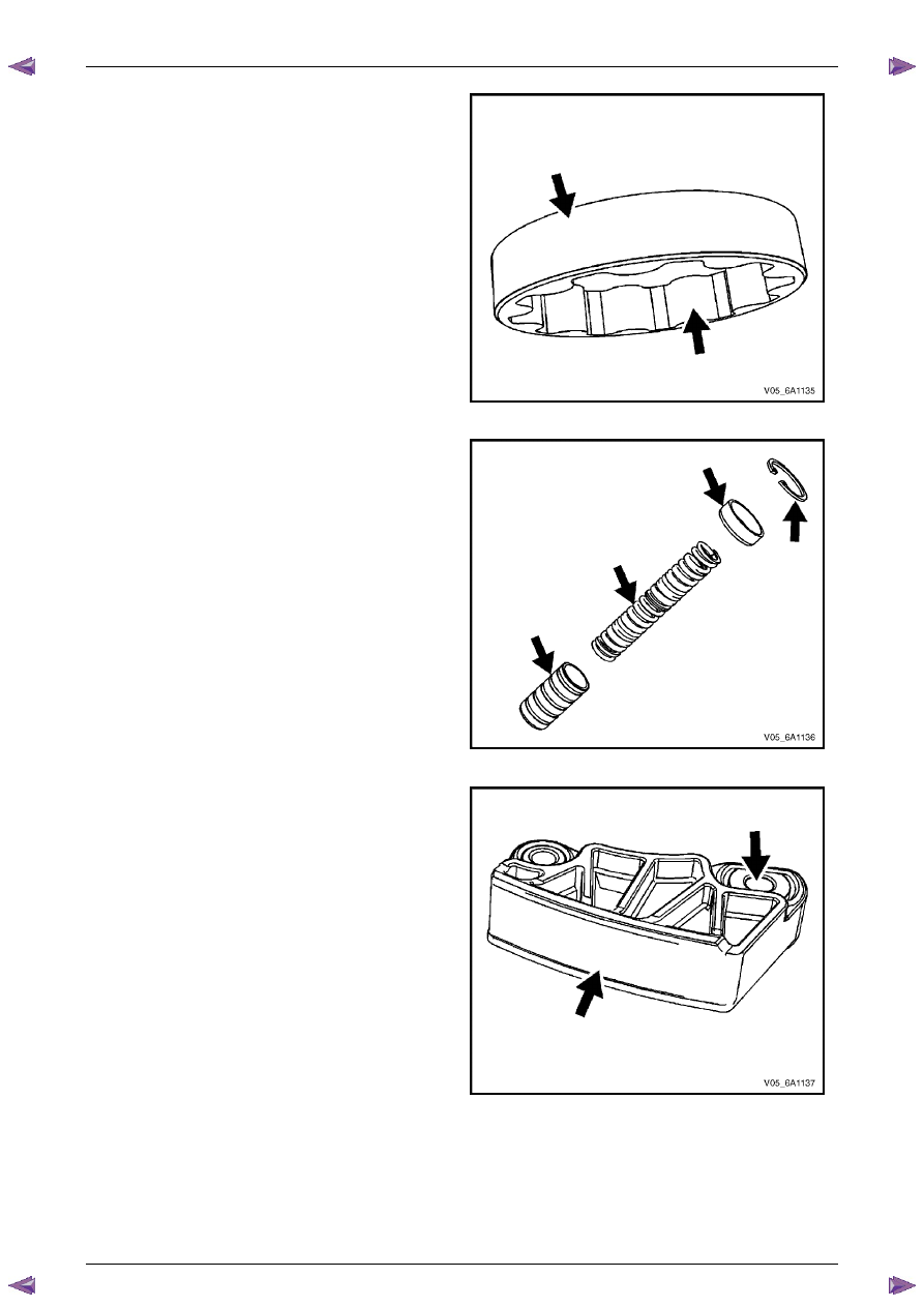
Inspect the outer driven gear for damage.
Figure 6A1 – 294
5
Inspect the oil pump relief valve components for
debris or damage.
Figure 6A1 – 295
6
Inspect the primary camshaft chain lower guide for
damage. If replacement of the primary camshaft chain
lower guide is required, replace the entire oil pump
assembly as the primary camshaft chain lower guide
is not serviceable separately.
7
If debris or damage is present within the oil pump,
further inspection of all of the engine components is
required.
Figure 6A1 – 296
Engine Mechanical – V6
Page 6A1–185
Page 6A1–185
Reassemble
CAUTION
As there are no serviceable components
within the oil pump, a disassembled oil pump
must be replaced.
Reinstall
1
Align the oil pump gerotor with the crankshaft flats
and fit the oil pump assembly to the engine block.
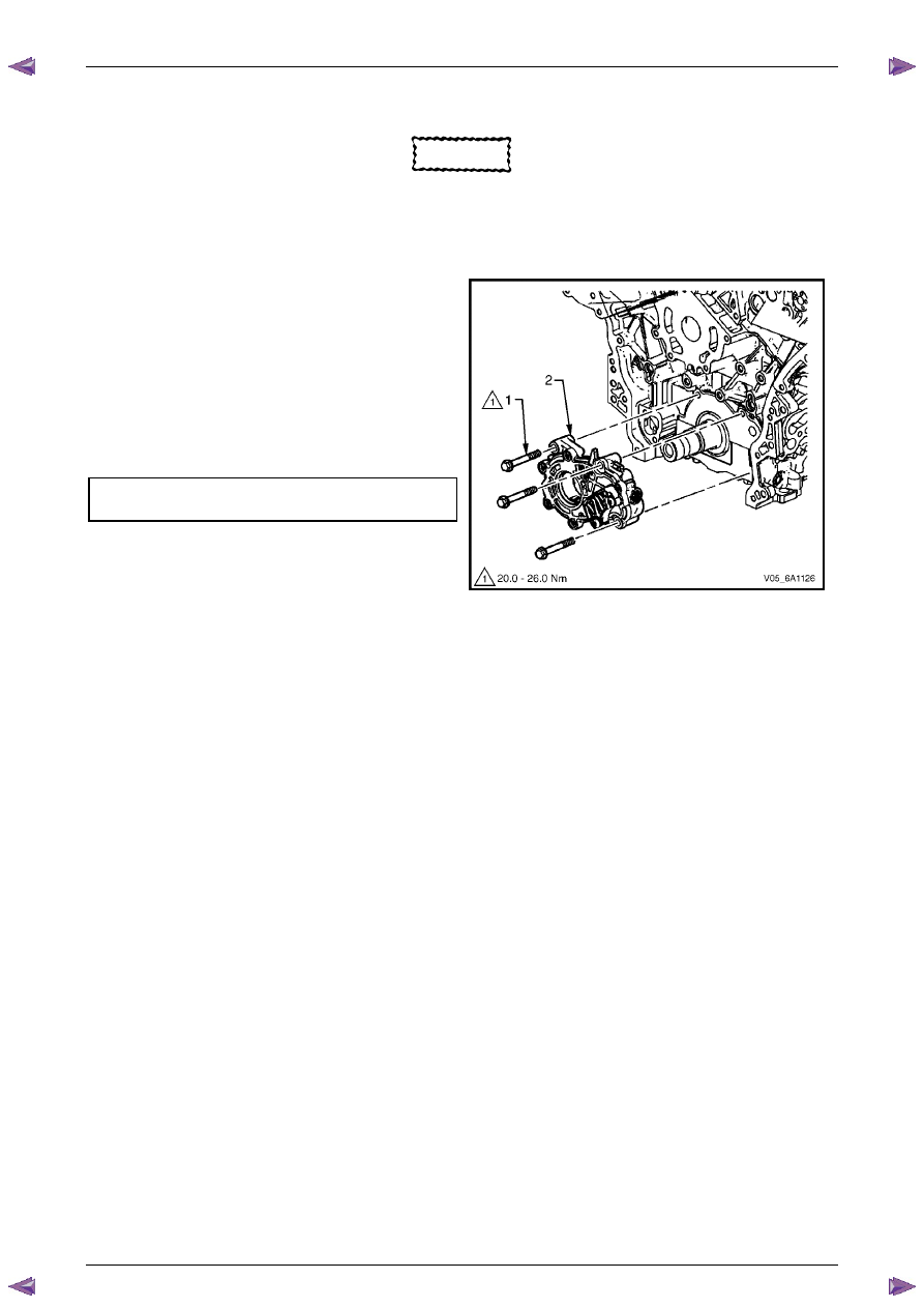
2
Align the pump body (2) with the mounting holes in
the cylinder block.
3
Install the oil pump bolt (1), three places, and tighten
to the correct torque specification.
4
Install the primary timing chain, refer to
3.16 Timing
Chains, Tensioners, Shoes and Guides
.
Oil pump attaching bolt torque
specification . . . . . . . . . . . 20.0 – 26.0 Nm
Figure 6A1 – 297

Engine Mechanical – V6
Page 6A1–186
Page 6A1–186
3.18 Camshaft Sprocket – Excluding MY06
Update
CAUTION
Setting the camshaft timing is required
whenever the camshaft drive system is
disturbed to ensure the relationship between
any chain and sprocket is not lost. Even when
only one sprocket is involved, multiple
crankshaft rotations will not produce
conditions where correct timing can be
confirmed.
If required, follow the Left-hand Secondary
Camshaft Chain Components reinstallation
procedure to reset the camshaft timing.
Remove
Right-hand Side
1
Remove the right-hand camshaft cover, refer to
3.12 Camshaft Cover
.
2
Remove the camshaft position sensors, refer to
Section 6C1-3 Engine Management – Service Operations
.
3
Remove the camshaft position actuator solenoids, refer to
Section 6C1-3 Engine Management – V6 – Service
Operations
.
4
Remove the crankshaft balancer assembly, refer to
3.13 Crankshaft Balancer Assembly
.
5
Install the crankshaft rotation socket Tool No.
EN-46111 onto the crankshaft.
6
Rotate the crankshaft until the camshafts are in a
neutral low tension position. The camshaft flats will be
parallel with the camshaft cover rail (1).
Figure 6A1 – 298
Нет комментариевНе стесняйтесь поделиться с нами вашим ценным мнением.
Текст