Isuzu KB P190. Manual — part 741
Engine Mechanical – V6
Page 6A1–187
Page 6A1–187
7
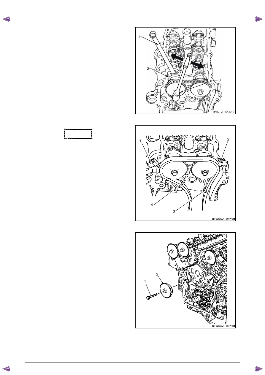
Install Tool No. EN-46105 – 1 (1) onto the rear of the
right-hand cylinder head (3) camshafts (2).
Figure 6A1 – 299
N O T E
Use an open-end spanner (1) at the camshaft
hex (2) to prevent camshaft/engine rotation.
N O T E
Do not remove the camshaft sprocket bolt (3) at
this time.
8
Loosen the camshaft sprocket bolt (3).
N O T E
If you have already removed the camshaft
timing chain proceed to step 12
Figure 6A1 – 300
Engine Mechanical – V6
Page 6A1–188
Page 6A1–188
CAUTION
Ensure the tips of Tool No.
EN-46108 are fully engaged into the timing
chain and the wing nuts are tight and the
timing chain is taught.
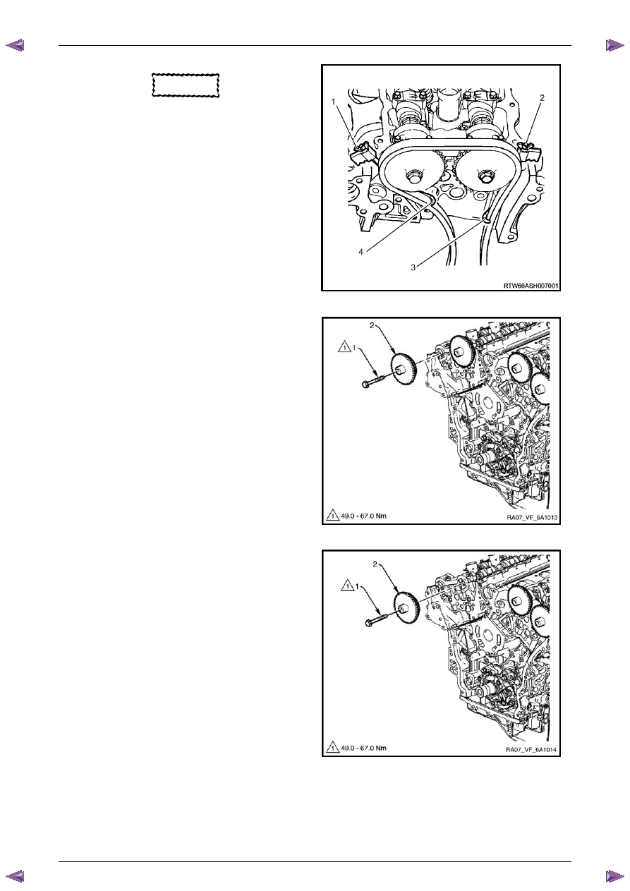
9
Install Tool No. EN-46108 (1 and 2) to retain the
timing chain (3 and 4).
10
Firmly tighten the wing nuts of Tool No. EN-46108.
11
Mark the timing chain and the respective location on
both camshaft sprocket.
N O T E
Ensure the camshaft timing chain and the
camshaft sprocket are marked for correct
reassembly.
Figure 6A1 – 301
12
Remove the bolt (1) attaching the right-hand exhaust
camshaft sprocket (2) and remove the sprocket.
Figure 6A1 – 302
13
Remove the bolt (1) attaching right-hand intake
camshaft sprocket (2) and remove the sprocket.
Figure 6A1 – 303
Engine Mechanical – V6
Page 6A1–189
Page 6A1–189
Left-hand Side
1
Remove the left-hand camshaft cover, refer to
3.12 Camshaft Cover
.
2
Remove the camshaft position sensors, refer to
Section 6C1-3 Engine Management – V6 – Service Operations
.
3
Remove the camshaft position actuator solenoids, refer to
Section 6C1-3 Engine Management – V6 – Service
Operations
.
4
Remove the crankshaft balancer assembly, refer to
3.13 Crankshaft Balancer Assembly
.
5
Install the crankshaft rotation socket Tool No.
EN-46111 onto the crankshaft.
6
Rotate the crankshaft until the camshafts are in a
neutral low tension position. The camshaft flats will be
parallel with the camshaft cover rail (1).
Figure 6A1 – 304
7
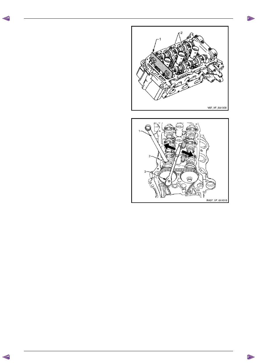
Install Tool No. EN-46105 – 1 (1) onto the rear of the
left-hand cylinder head camshafts (2).
Figure 6A1 – 305
Engine Mechanical – V6
Page 6A1–190
Page 6A1–190
N O T E
Use an open-end wrench (1) at the camshaft
hex (2) to prevent camshaft/engine rotation.
N O T E
Do not remove the camshaft sprocket bolt (3) at
this time.
8
Loosen the camshaft sprocket bolt (3).
N O T E
If the camshaft timing chain has already been
removed proceed to Step 12.
Figure 6A1 – 306
CAUTION
Ensure the tips of Tool No. EN-46108 are
fully engaged into the timing chain and the
wing nuts are tight and the timing chain is
taught.
9
Install Tool No. EN-46108 (1 and 2) to retain the
timing chain (3 and 4).
10
Firmly tighten the wing nuts of Tool No. EN-46108.
N O T E
Ensure the camshaft timing chain and the
camshaft sprocket are marked for correct
reassembly.
11
Mark the timing chain and the respective location on
both camshaft sprocket.
Figure 6A1 – 307
12
Remove the bolt (1) attaching the left-hand exhaust
camshaft sprocket (2) and remove the sprocket.
Figure 6A1 – 308
Нет комментариевНе стесняйтесь поделиться с нами вашим ценным мнением.
Текст