Isuzu KB P190. Manual — part 803
Fuel System – V6
Page 6C – 10
After relieving the fuel system pressure, a
small amount of fuel may be released when
servicing the fuel lines or connections. Cover
the fittings with a shop towel before
disconnecting. This catches any leaking fuel.
Place the soiled towel in an approved
container when disconnection is completed.
3
Wrap a shop towel around the fuel pressure test point to absorb any fuel spillage.
4
Remove the fuel pressure gauge and drain any fuel remaining in the fuel pressure gauge into an approved fuel
container.
5
Remove the soiled shop towel and place in an approved container.
6
Repressurise the fuel system, refer to 3.4
Fuel System Depressurisation.
7
Road-test the vehicle and check for correct operation.
3.3
Fuel Leak Test
After installing any fuel system component
and before starting the engine, check the fuel
system for leaks.
N O T E
For the fuel injector leak-down test (for vehicles
fitted with a V6 engine), refer to 6C1-3 Engine
Management – V6 – Service Operations.
1
Turn the ignition switch on for two seconds.
2
Turn the ignition switch off for 10 seconds.
3
Turn the ignition switch on.
4
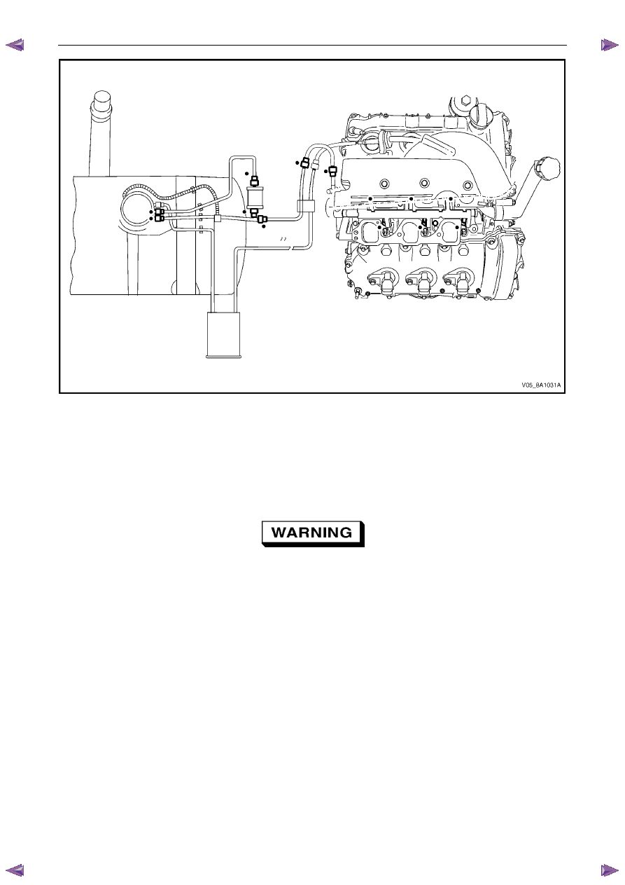
Check for fuel leaks, particularly at points marked
z (that is, quick-connect fittings, fuel rails, fuel injectors,
Schrader valve and evaporative emission control canister purge solenoid, refer to Figure 6C – 6.
Fuel System – V6
Page 6C – 11
Figure 6C – 6
5
Replace any faulty components and repeat step 2 to step 5 inclusive.
6
Replace all engine components removed to perform the fuel leak test, refer to 6C1-3 Engine Management – V6 –
Service Operations.
3.4
Fuel System Depressurisation
To reduce the risk of fire or personal injury,
depressurise the fuel system before servicing
any fuel system components.
1
Turn the ignition switch off.
2
Remove the fuel pump fuse and fuel pump relay, refer to 8A Electrical Body and Chassis.
3
Loosen the fuel filler cap to relieve the fuel tank vapour pressure.
4
With the throttle closed, crank the engine.
N O T E
The engine may start and operate until the fuel
remaining in the fuel delivery system depletes.
5
When the engine stops, crank the engine for another 10 seconds to ensure the fuel feed line pressure has been
fully relieved.
6
Clean the area around the fuel pressure test point.
Fuel System – V6
Page 6C – 12
A small amount of fuel may be released when
pressing on the Schrader valve. Cover the
fitting with a shop towel to absorb any fuel
spillage before removing the Schrader valve
sealing cap. Place the soiled towel in an
approved container for disposal.
7
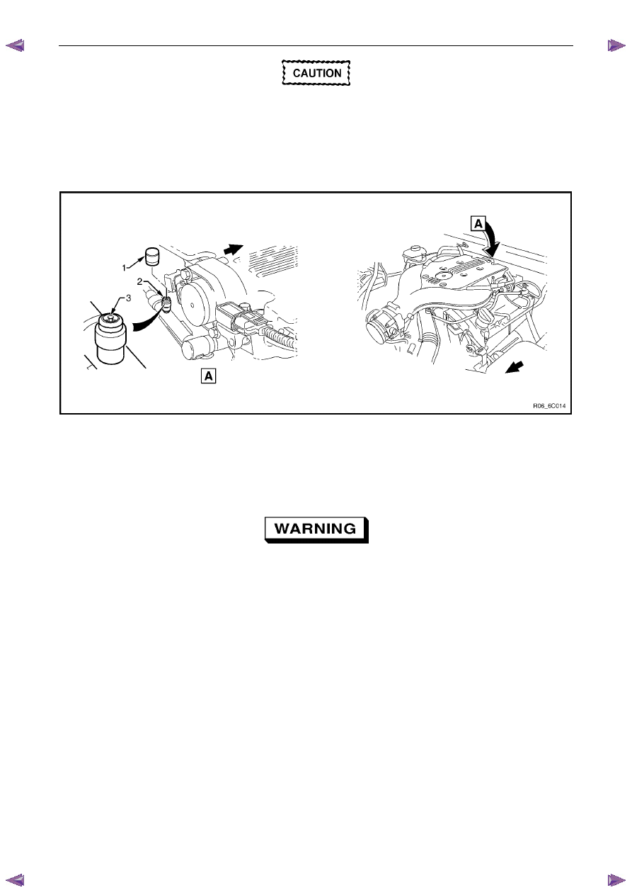
At the fuel pressure test point (2), remove the Schrader valve sealing cap (1), refer to Figure 6C – 7.
Figure 6C – 7
Legend
1
Schrader Valve Sealing Cap
2
Pressure Test Point
3 Schrader
Valve
Wear safety glasses when performing the fuel
pressure relief procedure.
8
Place a shop towel around the Schrader valve to soak up the expelled petrol.
9
Use a small screwdriver to press the Schrader valve down (3).
10
Remove the soiled shop towel and place in an approved container.
Repressurise
1
Reinstall the fuel pump relay and fuel pump fuse.
2
Perform the following procedure to inspect for leaks at the fuel pressure test point:
a
Turn the ignition switch on for two seconds.
b
Turn the ignition switch off for 10 seconds.
c
Turn the ignition switch on.
d
Check for leaks at the fuel pressure test point.
3
Tighten the fuel filler cap.
4
Start the engine and recheck for leaks.
5
Reinstall the Schrader valve sealing cap.

Fuel System – V6
Page 6C – 13
4 Service
Operations
4.1
Fuel Lines And Quick Connect Fittings
Description
The fuel line connector fittings contain the following
components:
1 O-rings
2
Fuel line port
3 Connector
4
Plastic fuel line tube
Figure 6C – 8
Leak Test and Inspection
1.
Turn the ignition key to the ON position and ensure the fuel pump runs for a short time by listening for the pump
start up sound. The fuel pressure will increase when the fuel pump is actuated.
2
Perform a preliminary check of the system by inspecting the system for any leaks around the connections and
fittings.
3
Perform steps 1 and 2 several times.
4
If the preliminary check of the system produces no leaks, start the engine and check the system again for any sign
of leaks around the connections and lines.
Ensure all service precautions have been
observed prior to removing any connector
fittings.
Нет комментариевНе стесняйтесь поделиться с нами вашим ценным мнением.
Текст