Isuzu KB P190. Manual — part 802
Fuel System – V6
Page 6C – 6
Fuel Pump
Single Turbine Fuel Pump
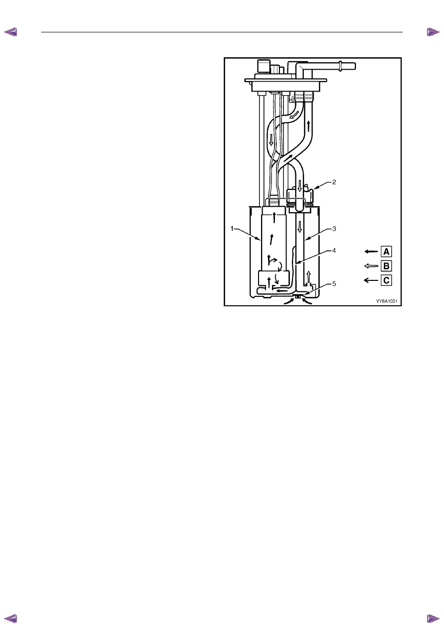
The fuel pump is an integral part of the Fuel Pump and Sender Assembly, refer to Figure 6C – 3.
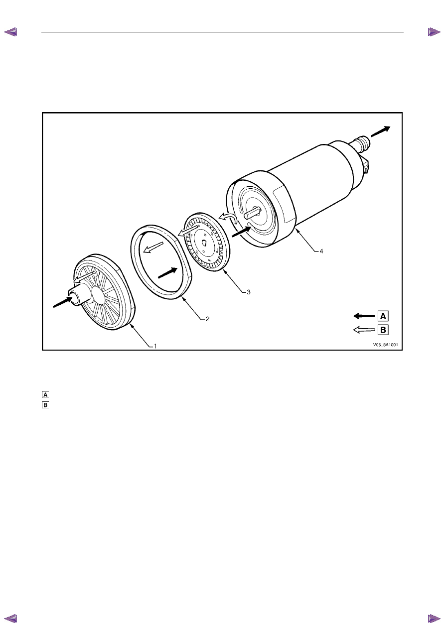
Figure 6C– 2 details the fuel flow through the single turbine fuel pump.
Figure 6C– 2
Legend
Fuel
Vapour
out
1 Inlet
Body
2 Impeller
Housing
3 Impeller
4
Fuel Pump Housing
Fuel System – V6
Page 6C – 7
Fuel Flow
Fuel (A) is drawn into the modular fuel pump and sender
assembly reservoir from the fuel tank, through the primary
umbrella valve (5) and into the fuel pump impeller, via the
internal strainer (4) at the fuel pump (1) inlet. At the impeller,
vapour (C) is separated from the fuel. The vapour is ejected
from the fuel pump into the reservoir via a port next to the
fuel pump inlet.
High-pressure fuel then flows through the end cap, the lower
connector and the flexible line. From the flexible line, fuel
exits the modular fuel pump and sender assembly through
the fuel feed port and flows on to the externally-mounted
fuel filter and the engine.
A fuel pressure regulator is located in the modular fuel pump
and sender assembly; fuel not used by the engine (B) is
returned to the modular fuel pump and sender assembly via
the fuel return line and the fuel return port in the modular
fuel pump and sender assembly cover. The return fuel
enters the jet pump standpipe (3) of the reservoir via the
return fuel tube.
Vehicle fuel line pressure is maintained by a pressure
regulator (2) located within the modular fuel pump and
sender assembly.
When the engine is switched off, the reservoir remains full of
fuel, due to the action of the primary umbrella valve. At high
fuel levels, fuel tank overflow enters the reservoir over the
top of the reservoir. Fuel level in the reservoir is also
maintained by returned engine fuel.
Electrical power is supplied to the fuel pump by a connector
secured to the modular fuel pump and sender assembly
cover. An internal harness (not shown) assembly completes
the connection to the pump.
Figure 6C – 3
Fuel System – V6
Page 6C – 8
3 System
Checks
3.1
Fuel Pump Flow Test
If a reduction of the fuel supply is suspected, perform the following checks.
1
Ensure there is sufficient fuel in the tank.
2
With the engine running, check the fuel lines from the
fuel tank to the injectors for evidence of leakage.
Retighten, if the lines or the connections are loose.
Also, check the fuel lines for restrictions such as
squashed or clogged fuel line.
3
Depressurize the fuel system, refer to 3.4
Fuel
System Depressurisation.
4
Disconnect the fuel line at the fuel rail.
5
Connect a hose from the fuel line and place the open
end into a clean container.
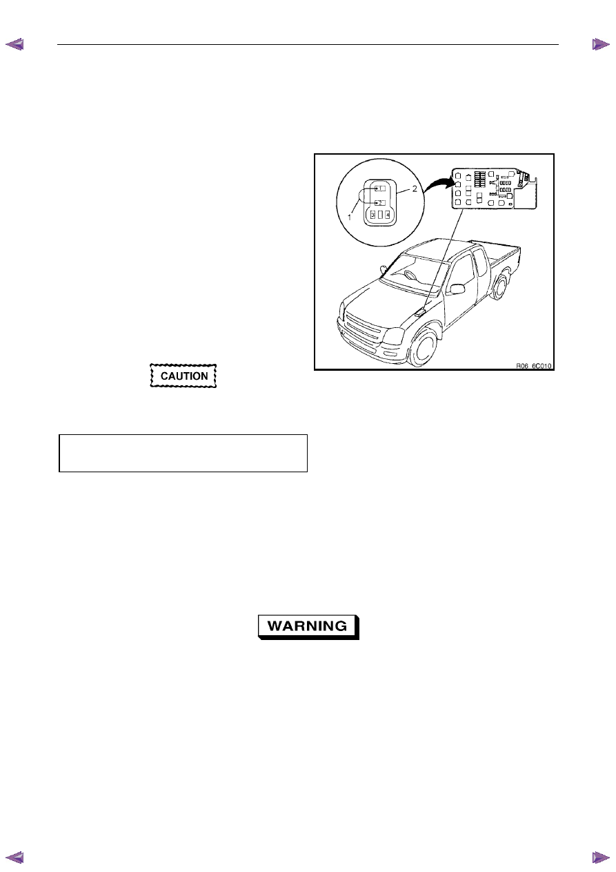
6
Connect the fuel pump relay terminals (2) with a
jumper wire (1) as shown, then turn the ignition to the
ON position to operate the fuel pump, then check the
fuel pump flow rate.
Do not generate any sparks when connecting
the jumper wire.
Fuel delivery test time . . . . . . . . . ... 15.0 Sec
Fuel delivery rate . . . . . . . . . .0.38 Litres Min
N O T E
If the fuel flow rate is below the minimum value,
conduct a fuel pressure test, refer to 3.2
Fuel Pressure Test.
Figure 6C – 4
3.2
Fuel Pressure Test
To reduce the risk of fire or personal injury,
depressurise the fuel system before servicing
any fuel system components, refer to 3.4
Fuel System Depressurisation.
Gauge Installation
1
Turn the ignition switch off.
2
Depressurise the fuel system, refer to 3.4
Fuel System Depressurisation.
Fuel System – V6
Page 6C – 9
A small amount of fuel may be released when
connecting the fuel pressure gauge to the fuel
pressure test point. Cover the fittings with a
shop towel to absorb any fuel spillage before
connecting the fuel pressure gauge. After the
fuel pressure test procedure, place the soiled
towel in an approved container for disposal.
3
At the fuel pressure test point, remove the Schrader valve sealing cap.
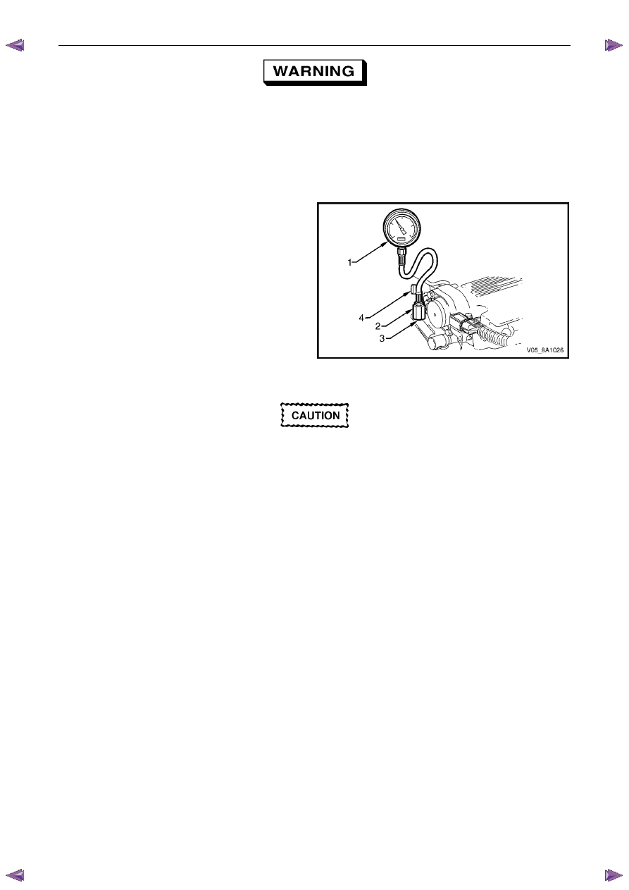
4
Connect the fuel pressure gauge (1) (tool
No. J 34730–1A) to the fuel gauge Schrader fitting
adapter (2) (tool No. AU453), then install to the fuel
pressure test port (3). Wrap a shop towel around the
fitting while connecting the fuel pressure gauge to
avoid and/or capture any fuel spillage.
5
Route the bleed hose of the fuel gauge into an
approved fuel container.
Figure 6C – 5
After connecting the fuel pressure gauge and
pressurising the fuel system, inspect for fuel
leaks at the fuel pressure gauge and the fuel
pressure test point.
6 Either:
Using Tech 2, enable the fuel pump to pressurise the fuel system, refer to 0C Tech 2. Inspect for fuel leaks at the
fuel pressure gauge and fuel pressure test point, then bleed the air from the fuel pressure gauge.
or:
Reinstall the fuel pump relay and fuel pump fuse, then open the fuel gauge bleed valve (4) to bleed the air from the
fuel pressure gauge, refer to Figure 6C – 5.
7
Remove and place the soiled shop towel in an approved container.
Test
1
Start the engine and record the fuel pressure.
2
Turn the ignition switch off.
3
If required, perform any tests and/or diagnostic procedures:
•
For the fuel system leak test, refer to 3.3 Fuel Leak Test.
•
For the fuel injector leak-down test (for vehicles fitted with a V6 engine, refer to 6C1-3 Engine Management –
V6 – Service Operations.
4
Depressurise the fuel system, refer to 3.4
Fuel System Depressurisation.
Removal
1
Turn the ignition switch off.
2
Depressurise the fuel system, refer to 3.4
Fuel System Depressurisation.
Нет комментариевНе стесняйтесь поделиться с нами вашим ценным мнением.
Текст