Isuzu KB P190. Manual — part 794
Engine Cooling – V6 Engine
Page 6B1–41
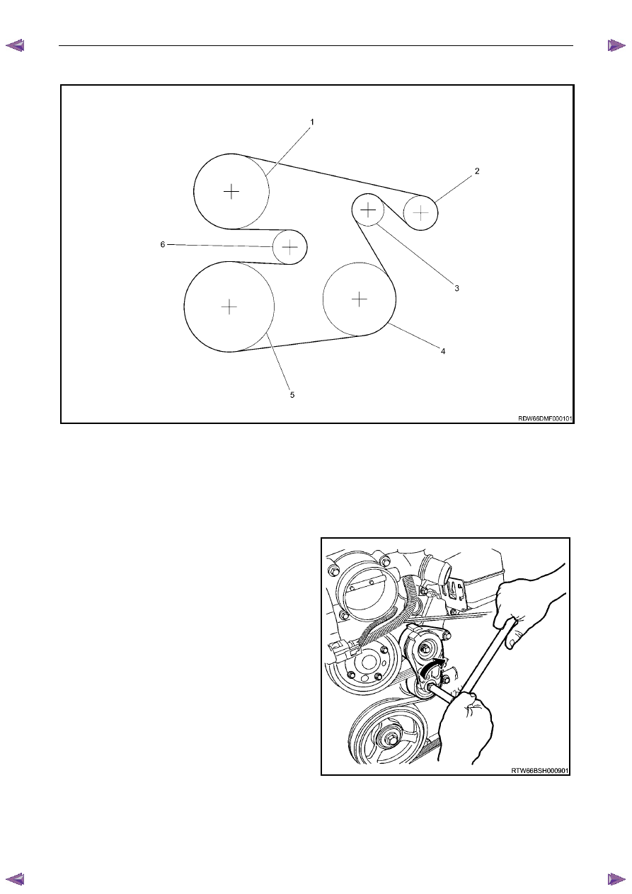
Figure 6B1 – 42 shows the drive belt routing for the HFV6 engine without air conditioning.
Figure 6B1 – 43
Legend
1 Coolant
Pump
2 Generator
3 Idler
4 Power
Steering
5 Crankshaft
6 Tensioner
4
Remove the drive belt from the coolant pump
pulley:
a
Rotate the drive belt tensioner pulley
clockwise (arrow) using a 1/2” drive
extension in order to release the drive
belt tension.
b
Remove the drive belt from the coolant
pump pulley.
c
Slowly release the drive belt tensioner.
Figure 6B1 – 44
Engine Cooling – V6 Engine
Page 6B1–42
5
Drain the coolant from the system. Refer to 3.3
Draining and Filling Cooling System in this
Section.
6
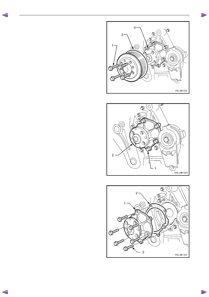
Remove the four coolant pump pulley attaching
bolts (1), then remove the pulley (2) from the
hub (3).
Figure 6B1 – 45
7
Remove the six coolant pump attaching bolts (1)
from the coolant pump (2).
Figure 6B1 – 46
8
Remove the coolant pump (1) from the engine front
cover.
N O T E
If necessary, use a soft-faced hammer to
lightly tap coolant pump housing to separate it
from front cover.
9
Remove coolant pump to front cover gasket (2) and
discard.
Figure 6B1 – 47
Engine Cooling – V6 Engine
Page 6B1–43
Inspect
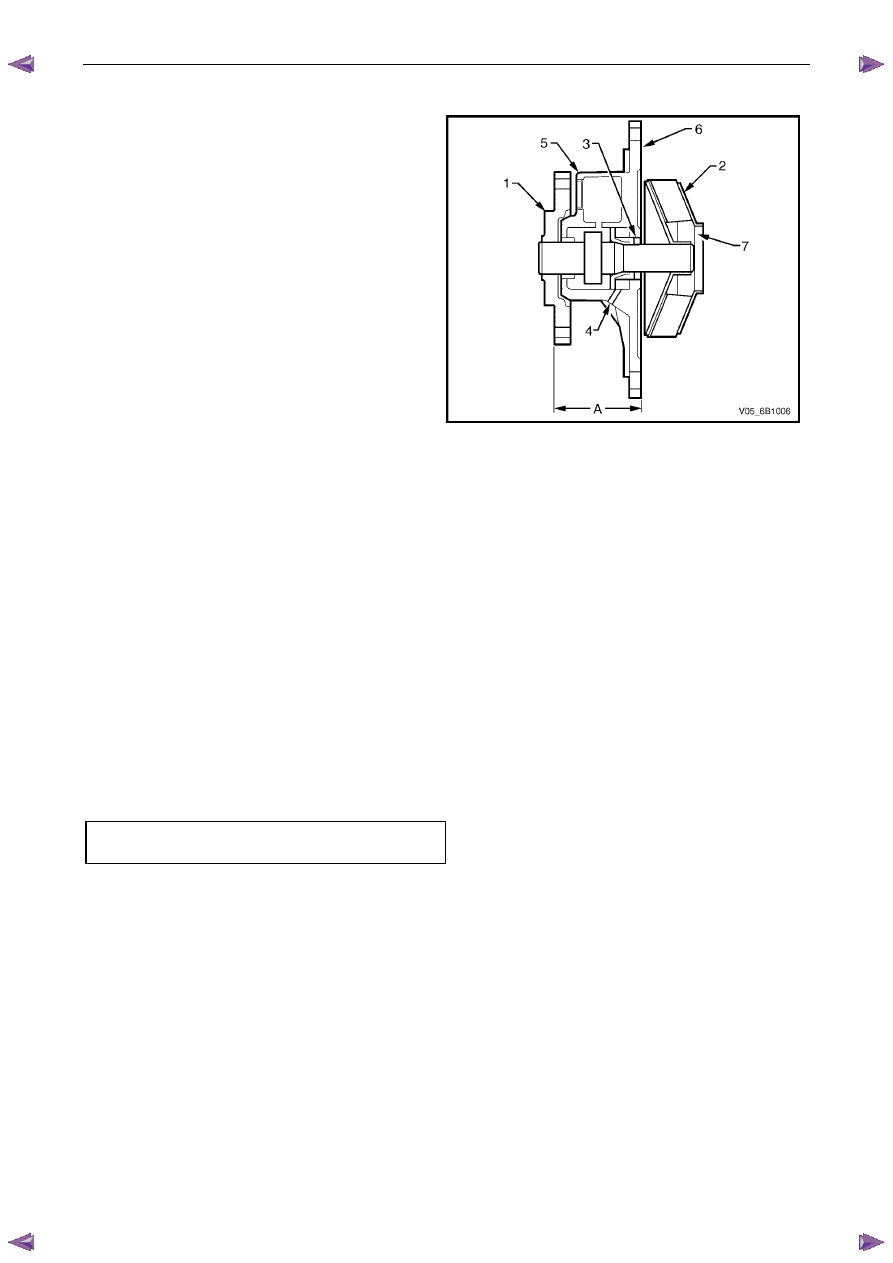
1
Rotate the coolant pump hub (1). The hub and
impeller (2) should turn straight and smoothly. If the
hub wobbles, is noisy or feels rough when rotated,
replace the coolant pump.
2
Inspect the exterior of the coolant pump for the
following:
• Damage to the coolant pump hub bolt threads
for the coolant pump pulley
• Damage to the coolant pump bolt holes
3
Examine the coolant pump shaft (3) and the weep
hole (4) in the coolant pump housing (5) for signs of
leakage. If coolant leakage is evident, replace the
coolant pump.
4
Inspect the interior of the coolant pump for the
following:
Figure 6B1 – 48
• Damage to the coolant pump gasket-sealing flange surface (6)
• Damage, corrosion or restrictions to the coolant pump impeller
• Damage, corrosion or restrictions to the coolant passages (7)
N O T E
Hub Flange to rear of Pump Housing
measurement (A) should be 44
± 0.25 mm.
5
Replace the coolant pump as necessary.
Reinstall
1
Ensure that the coolant pump and front cover mating surfaces are clean and dry.
2
Install a new gasket to the front cover.
3
Clean threads of coolant pump to front cover and cylinder block attaching bolts.
4
Install coolant pump and attaching bolts. Tighten all bolts to the correct torque specification.
Coolant pump to front cover
bolt torque specification . . . . . . . . . ...10 N.m
Engine Cooling – V6 Engine
Page 6B1–44
5
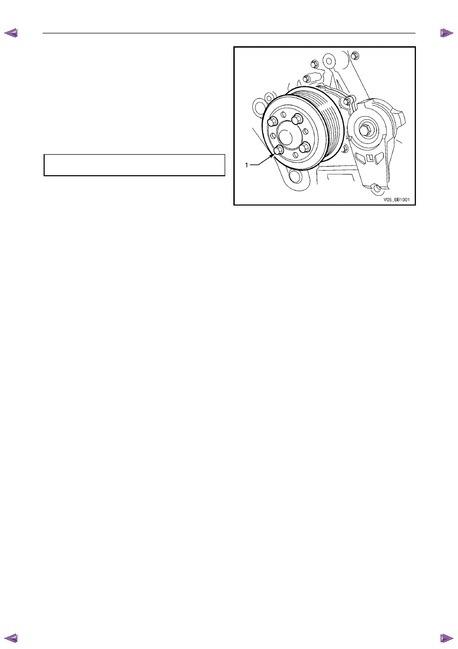
Install coolant pump pulley and attaching bolts (1).
6
Install drive belt (reverse to removal procedures) and
ensure that the drive belt is aligned with all accessory
pulleys and crankshaft balancer drive belt grooves.
N O T E
Refer to Figure 6B1 – 43, as required for the
correct drive belt routing.
7
Tighten coolant pump pulley attaching bolts (1) to the
correct torque specification.
Coolant pump pulley to hub
bolt torque specification . . . . . . . . ...12 N.m
8
Close the radiator drain tap on the lower LHS of the
radiator and remove the piece of rubber tubing to the
tap outlet.
Figure 6B1 – 49
9
Refill cooling system. Refer to 3.3 Draining and Filling Cooling System in this Section.
10
Check for coolant leaks. Refer to 3.7 Pressure Testing in this Section.
11
Install the radiator shroud.
12
Reconnect battery ground lead. Refer to 8A – Electrical Body & Chassis.
Нет комментариевНе стесняйтесь поделиться с нами вашим ценным мнением.
Текст