Isuzu KB P190. Manual — part 792

Engine Cooling – V6 Engine
Page 6B1–33
3
Install the coolant filler neck adaptor, to a
commercially available cooling system pressure tester
(1).
4
Install the assembly to the engine coolant filler neck.
5
Using compressed air, blow dry any spilled coolant
around coolant filler neck.
Do not exceed the stated pressure, as
damage to the cooling system could
otherwise result.
6
Using the cooling system pressure tester pump,
pressurise cooling system to 130 kPa absolute
maximum and check for leaks at the following points:
•
All hoses and hose connections
•
Overflow hose connection at coolant outlet
housing connection
Figure 6B1 –
––
– 32
•
Radiator seams and core
•
Corroded or faulty engine Welch plugs
•
Coolant pump and gasket
•
Thermostat housing and coolant inlet pipe connection
•
Radiator drain tap and bleed screw
•
Vehicle heating system (e.g. heater core and water valve)
N O T E
For heater Removal and Installation, refer to 2A –
Heater and Air-conditioning.
7
Check engine oil dipstick for evidence of engine oil contamination with coolant.
8
If pressure will not hold, there is a leak in the cooling system. Repair as necessary.
N O T E
If visible loss of coolant is not evident from
pressure testing, then the use of a dye and black
light, may be necessary. Refer to 4.7
Black
Light and Dye Leak Diagnosis Method, in this
Section.
Engine Cooling – V6 Engine
Page 6B1–34
3.8 Thermostat
Remove
Do not remove coolant filler cap while the
engine coolant temperature is above 50
°°°° C, as
personal injury may result.
1
Allow engine to cool to ambient temperature (less than 50
° C), then remove the coolant filler cap (located at the
front left-hand side of the engine).
Disconnection of the battery affects certain
vehicle electronic systems. Refer to 00
Warnings, Cautions and Notes, before
removing the ground lead.
2
Disconnect the battery ground lead. Refer to 6D1-3 Battery – V6.
Refer to ‘
‘
‘
‘ Environmental Issues ’
’
’
’ in 3.1
Service Notes, before draining the coolant.
3
Drain the coolant from the system. Refer to 3.3 Draining and Filling Cooling System in this Section.
4
Remove the complete intake manifold assembly. Refer to 6A1 Engine Mechanical – V6.
5
Plug each of the exposed intake ports with lint free cloth to prevent the entry of foreign matter.
6
Remove the coolant inlet pipe. Refer to 3.12
Coolant Inlet Pipe in this Section.
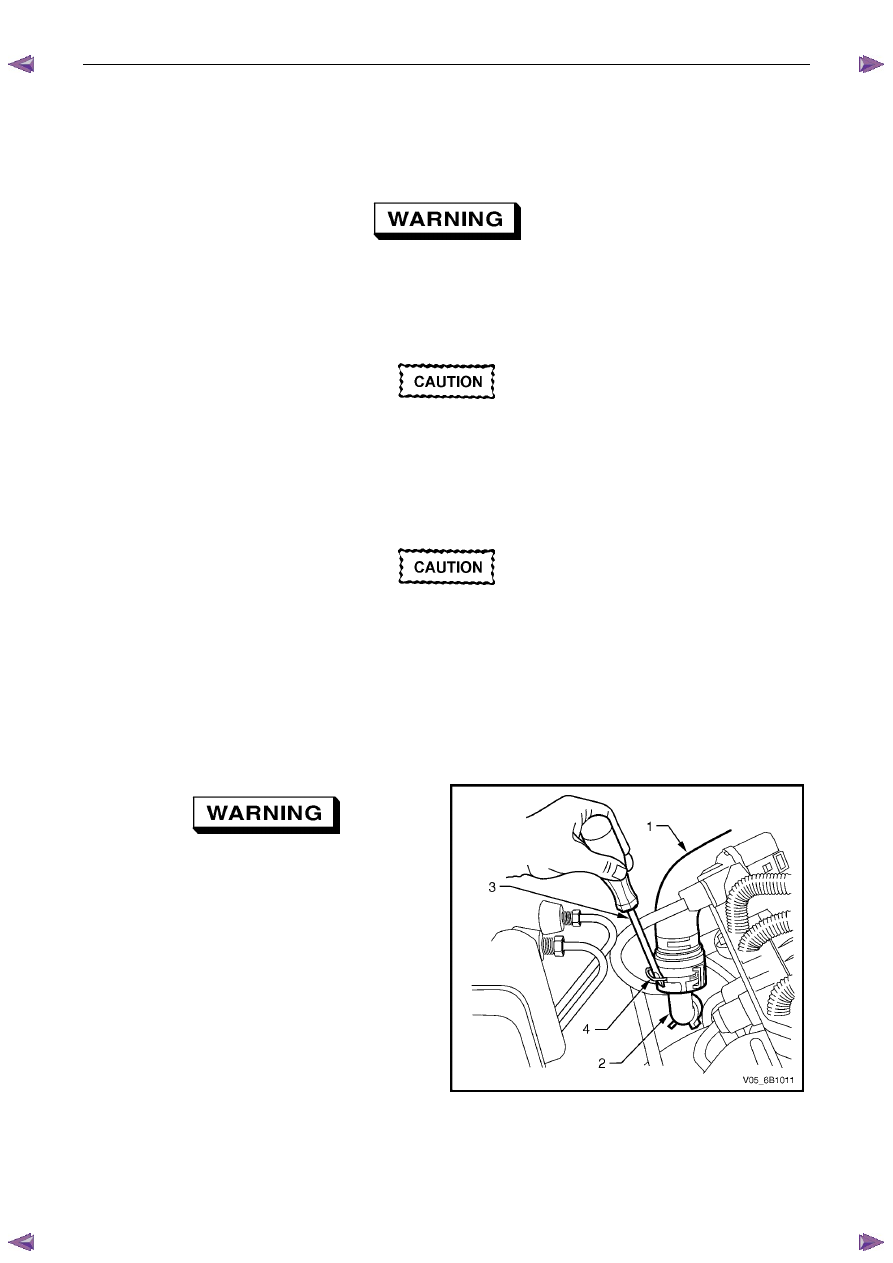
Always wear protective safety glasses when
working with spring type hose clamps.
Failure to do so could result in eye injury.
7
Use a straight-blade screwdriver (3) to release the
heater hose quick connect clips (4).
8
Disconnect the heater hoses (1) from the heater pipes
(2) in two places.
Figure 6B1 –
––
– 33
Engine Cooling – V6 Engine
Page 6B1–35
9
To gain easier access to the heater pipe flange and
thermostat housing bolts, disconnect the engine
harness and lay back on the right side of the engine
bay. Apart from those harness connectors removed
during the intake manifold removal, this involves the
removal of wiring harness connectors and fasteners,
as detailed:
a
Pull out the release bar (arrows) on each of the
ignition coil packs (1) on cylinders 2, 4 and 6,
before disconnecting each connector.
b
The coolant temperature sensor.
c
The left side Pre-O2 sensor connector, 2, 4 & 6.
N O T E
Refer to 8A – Electrical Body & Chassis for the
location of harness connectors, not shown.
Figure 6B1 –
––
– 34
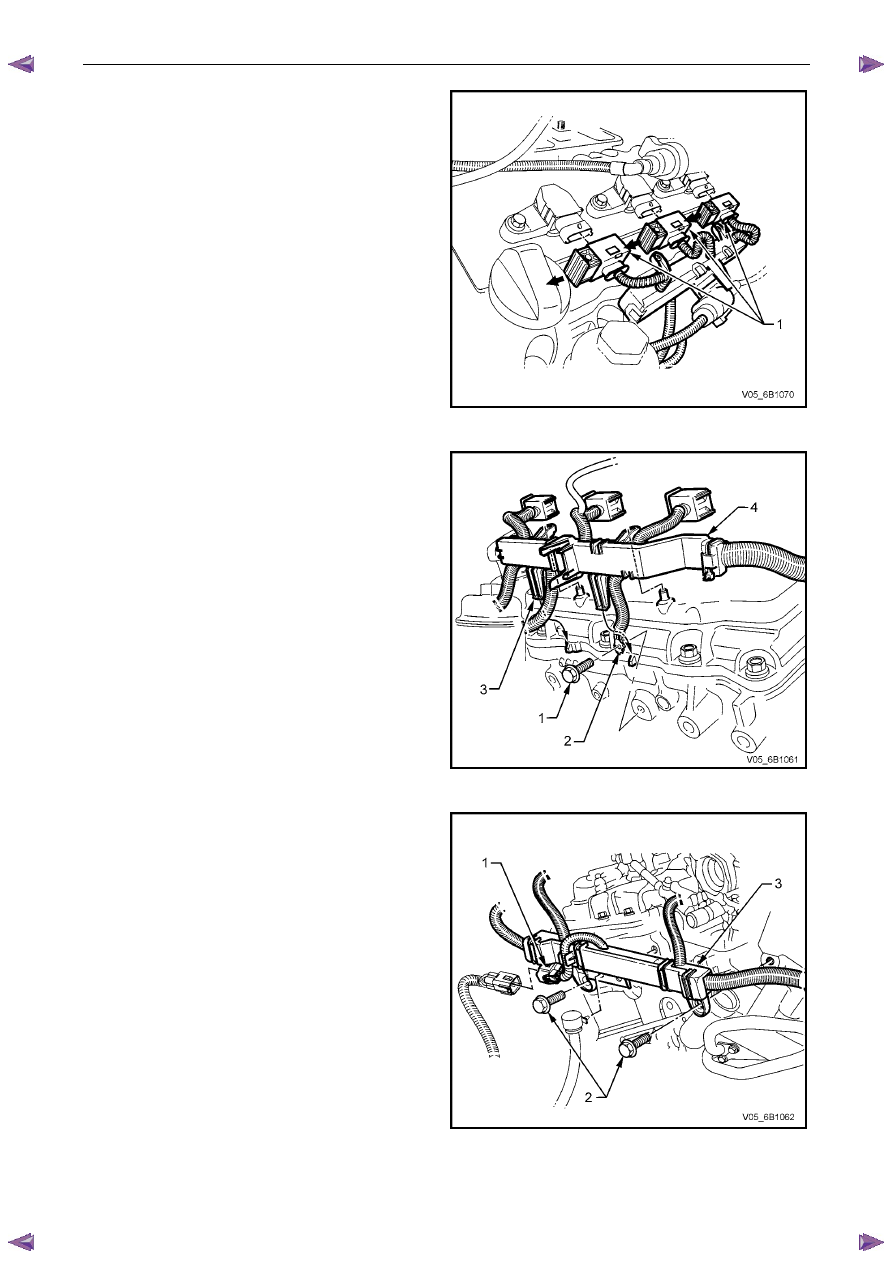
10
Remove the bolt (1) securing the engine harness
ground terminal (2), to the cylinder block.
11
Prise both locking legs of the left side engine harness
former (4), free, then lift up on the harness former to
release.
Figure 6B1 –
––
– 35
12
Working at the rear of the engine, disconnect the
engine harness to transmission harness connector (1),
as required.
13
Remove the two bolts (2) securing the engine harness
former (3) to the rear of the engine.
14
Carefully lift the engine harness free and drape on the
right side of the engine.
N O T E
For further information on removing the
thermostat housing and associated components,
refer to 6A1 Engine Mechanical – V6.
Figure 6B1 –
––
– 36
Engine Cooling – V6 Engine
Page 6B1–36
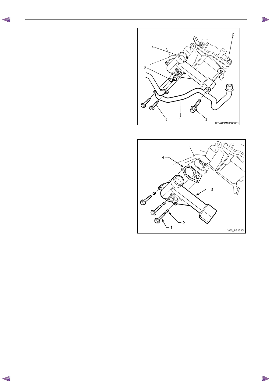
15
Remove the heater pipe assembly (1) to right-hand
side cylinder head (2) attaching bolt (3).
16
Remove the heater pipe assembly to thermostat
housing (4) attaching bolts (5), then remove the heater
pipe assembly.
17
Remove and discard the heater pipe assembly to
thermostat housing O-ring seals (6).
Figure 6B1 –
––
– 37
18
Remove the three thermostat housing attaching bolts
(1), rubber grommets (2), then remove the thermostat
housing (3).
N O T E
The upper thermostat housing attaching bolt is
longer than the two lower bolts.
19
Remove and discard the thermostat housing to engine
block gasket (4).
Figure 6B1 –
––
– 38
Нет комментариевНе стесняйтесь поделиться с нами вашим ценным мнением.
Текст