Isuzu KB P190. Manual — part 793
Engine Cooling – V6 Engine
Page 6B1–37
Test
1
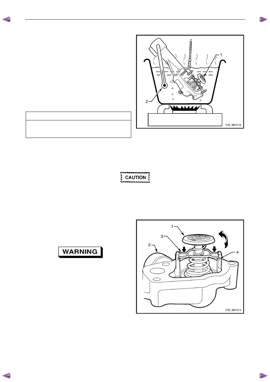
With the thermostat (1) installed in the housing,
suspend it and a suitable thermometer (2) in a
container of 50% clean fresh water and 50% Dexron ®
long life coolant, (conforming to GM 6277M).
N O T E
Neither the thermostat assembly (1) nor the
thermometer (2) should rest on the bottom of the
container because of uneven concentration of
heat at this point when the container is heated.
2
Heat container until thermostat begins to open. Agitate
solution to ensure uniform temperature. Note
temperature and ensure thermostat opens within
specified temperature range.
Thermostat Opening Specifications
Opening Temperature. . . . . . . . . . 82
° C
Fully Open Temperature . . . . . . . . . 95
° C
3
Replace thermostat if it does not meet these operating
conditions.
Figure 6B1 –
––
– 39
Dismantle
Only dismantle the thermostat if a reverse
flushing operation of the cylinder block is to
be carried out. If the testing operation
indicates that the thermostat is faulty, then
the housing and thermostat are only serviced
as an assembly.
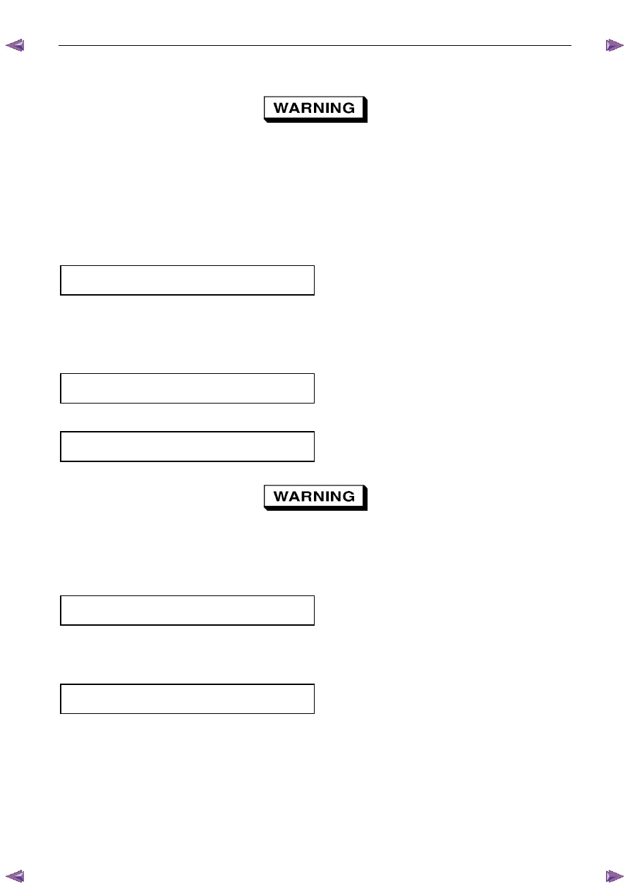
Remove thermostat (1) from thermostat housing (2) as
follows:
a
Secure the thermostat housing by gripping in a
vice fitted with soft jaws.
Always wear protective safety glasses when
working with spring-loaded devices. Failure
to do so could result in eye injury.
b
Depress the retaining bar (3) on both sides of the
thermostat and rotate the thermostat until it
clears the retaining lugs (4) on the thermostat
housing (2).
c
Release the thermostat spring force.
d
Remove the thermostat assembly from the
thermostat housing.
Figure 6B1 – 40
Reassembly
The reassembly process is the reverse to that used for disassembly, with the following exceptions:
1
Check that the valve sealing surface is undamaged.
2
Wipe the valve sealing surface to ensure a clean surface.
Engine Cooling – V6 Engine
Page 6B1–38
Install
Always wear protective safety glasses when
working with spring-loaded devices. Failure to
do so could result in eye injury.
1
Install the thermostat into the housing (reverse to removal procedure).
2
Ensure that the engine block and thermostat housing mating surfaces are clean and dry.
3
Install a new gasket to the thermostat housing.
4
Install the thermostat housing to the engine block and secure with the attaching bolts (with rubber grommets
installed). Tighten all bolts to the correct torque specification.
Thermostat housing to engine
block bolt torque specification . . . . . . . ..10 N.m
5
Ensure that the heater pipe assembly and thermostat housing mating surfaces are clean and dry.
6
Install new O-rings to the heater pipe assembly.
7
Install heater pipe assembly to thermostat housing and secure with the attaching bolts. Tighten all bolts to the
correct torque specification.
Heater pipe assembly to thermostat
housing bolt torque specification. . . . . . ..10 N.m
8
Install heater pipe assembly to right-hand cylinder head bolt. Tighten bolt to the correct torque specification.
Heater pipe assembly to cylinder
head bolt torque specification . . . . . . . ..35 N.m
Always wear protective safety glasses when
working with spring type hose clamps. Failure
to do so could result in eye injury.
9
Reinstall the engine wiring harness, securing the rear harness former to the rear of the engine with the two
retaining bolts, tightened to the correct torque specification.
Rear engine harness former
retaining bolts torque specification. . . . . ...15 N.m
10
Reinstall the left side engine harness former to the two locating pegs, then push inward to secure.
11
Reinstall the bolt securing the engine harness ground terminal, to the left side of the cylinder block and tighten to
the correct torque specification.
Engine harness ground terminal
attaching bolt torque specification. . . . . . 12 N.m
12
Reinstall each wiring harness connector to its correct location, ensuring that all security clips are installed correctly.
13
Connect the heater hoses to the heater pipe assembly.
14
Install the coolant inlet pipe. Refer to 3.12 Coolant Inlet Pipe in this Section.
15 Close the radiator drain tap on the lower LHS of the radiator and remove the piece of rubber tubing to the tap outlet.
16
Reinstall the complete intake manifold assembly. Refer to 6A1 Engine Mechanical.
17
Refill cooling system. Refer to 3.3 Draining and Filling Cooling System in this Section.
Engine Cooling – V6 Engine
Page 6B1–39
18
Check for coolant leaks. Refer to 3.7 Pressure Testing in this Section.
19
Install the radiator shroud.
20
Install the engine dress covers. Refer to 6A1 Engine Mechanical.
21
Reconnect battery ground lead. Refer to 8A_ Electrical Body & Chassis.
22
Road test the vehicle to check for correct operation.
3.9
Coolant Recovery Reservoir
Remove
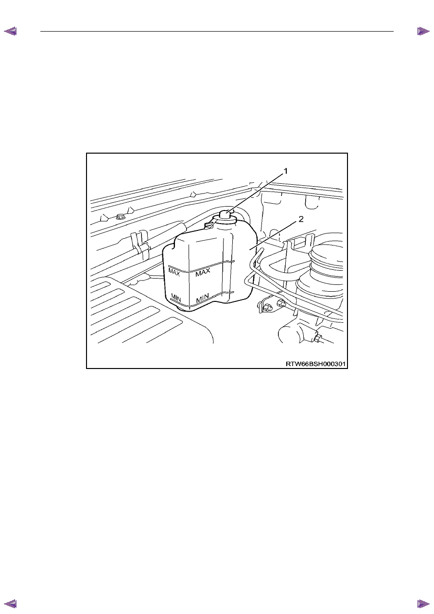
Figure 6B1 – 41
Legend
1 Filler
Cap
2 Reservoir
Remove the reservoir assembly attaching screws, and remove the reservoir assembly from the vehicle.
Inspect
1
Drain contents from reservoir assembly.
2
Clean the reservoir assembly with water and dry using compressed air.
3
Check reservoir and assembly for damage, for example abrasions, cracks or distortion. Replace if required.
Install
Installation of the reservoir assembly is the reverse of removal procedures, noting the following points:
1
Refill cooling recovery reservoir and cooling system with the correct concentration of coolant. Refer to 3.3 Draining
and Filling Cooling System in this Section.
Engine Cooling – V6 Engine
Page 6B1–40
2
Check coolant recovery system for leaks.
3.10 Coolant
Pump
Remove
Refer to 3.1 Service Notes in this Section, for
important safety items.
N O T E
The coolant pump is not to be disassembled and
is replaced only as an assembly.
1
Allow engine to cool to ambient temperature (less than 50
° C), and then remove the coolant filler cap (located at
the front left-hand side of the engine).
Disconnection of the battery affects certain
vehicle electronic systems. Refer to 1.1
WARNING, CAUTION and NOTES, before
removing the ground lead.
2
Disconnect the battery ground lead. Refer to 8A – Electrical Body & Chassis.
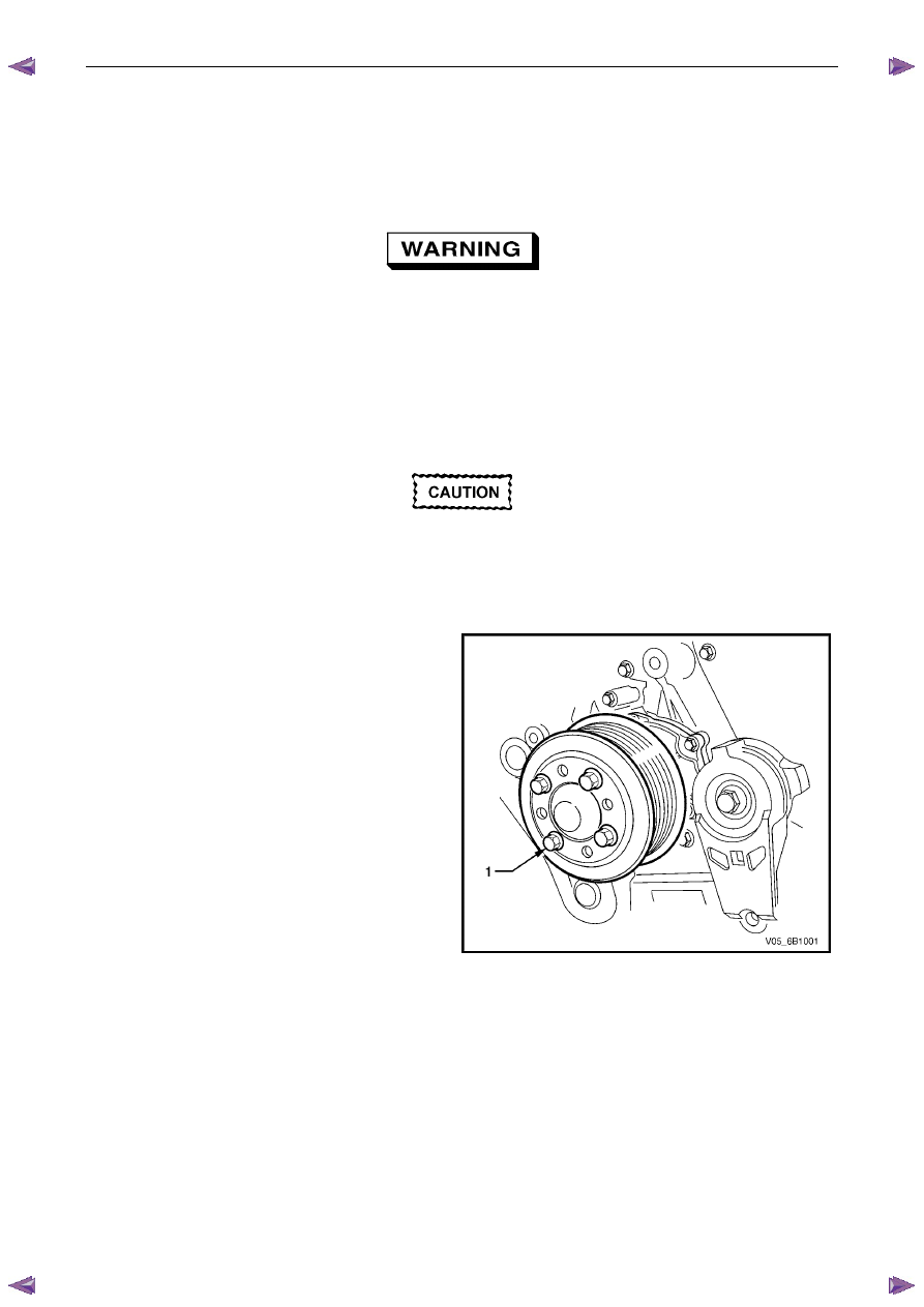
3
Loosen coolant pump pulley to hub bolts (1).
N O T E
While the view shows the drive belt removed,
it will be easier to loosen the four pulley bolts,
with the belt installed.
Figure 6B1 – 42
Нет комментариевНе стесняйтесь поделиться с нами вашим ценным мнением.
Текст