Isuzu KB P190. Manual — part 28
1-78 HEATER AND AIR CONDITIONING
RTW410MF000201

HEATER AND AIR CONDITIONING 1-79
CONTROL PANEL ILLUMINATION BULB
REMOVAL AND INSTALLATION
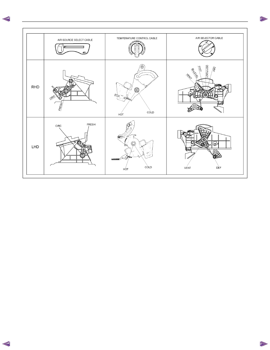
This illustration is based on RHD model
RTW710MF000401
Removal Steps
1. Control lever assembly
2. Illumination bulb
Installation Steps
2. Illumination bulb
1. Control lever assembly
1-80 HEATER AND AIR CONDITIONING
RTW710MH000101
Important Operations - Removal
1. Control lever assembly
Refer to “CONTROL LEVER ASSEMBLY” in this section.
2. Illumination Bulb
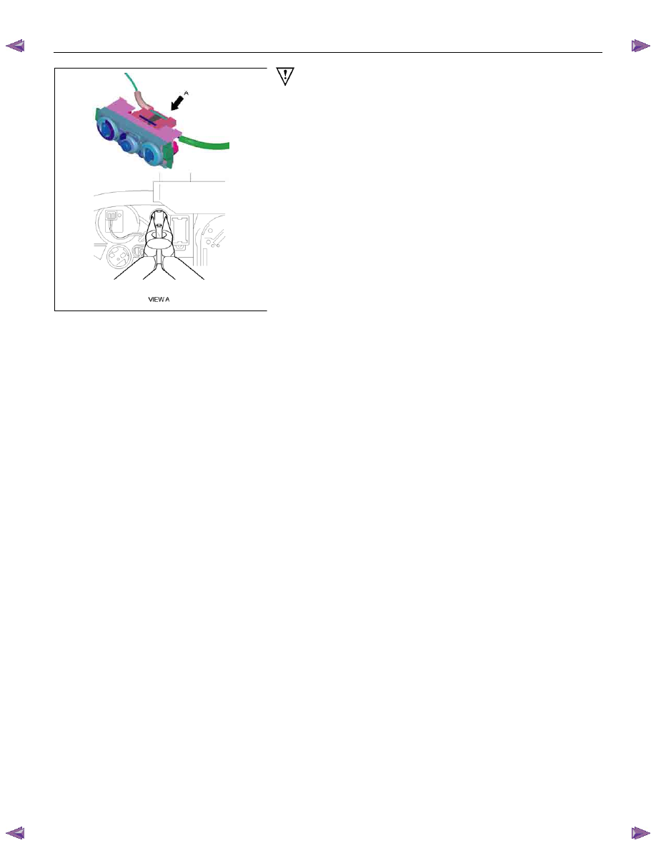
To remove the illumination bulb, insert a pliers (long nose) into
the cap at the back of the bulb. Turn the bulb counterclockwise
and pull it free.
HEATER AND AIR CONDITIONING 1-81
INSPECTION AND REPAIR
840R300005-X
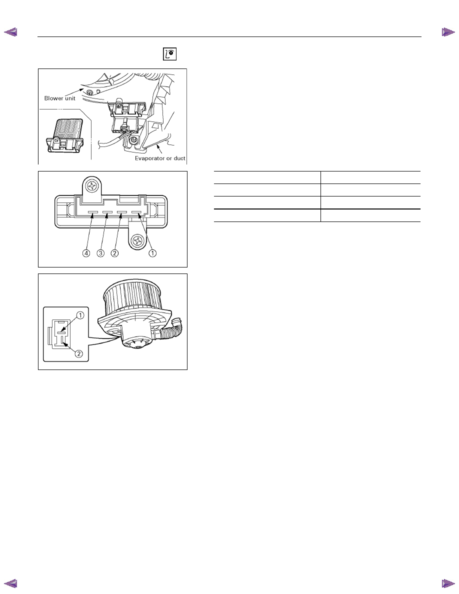
Resistor
As for air-conditioning model, fixed on left (RHD) / right (LHD)
side of the evaporator unit.
As for heater only model, fixed on left (RHD) / right (LHD) side
of the duct placed between blower unit and heater unit.
Replace the resistor with a new on if the coil is found to be
open or if the resistance value deviates from the specified
range.
Terminal Resistance
3 – 2
2.04
Ω
3 – 4
0.88
Ω
3 – 1
0.31
Ω
Blower motor
Check blower motor for smooth rotation.
Connect the battery positive terminal to the No.1 terminal of the
blower motor and negative to the No.2.
Be sure to check to see if the blower motor operates correctly.
Нет комментариевНе стесняйтесь поделиться с нами вашим ценным мнением.
Текст