Isuzu KB P190. Manual — part 908

Starting System – V6
Page 6D1-2–24
No Load Test
1
Clamp the starter motor securely to a test bench.
2
Connect the starter motor as shown in Figure 6D1-2 – 18, Close the start switch to activate the starter motor.
4
Record the speed of the planetary drive shaft, current draw and the voltage.
5
Check the readings are within the specifications.
Minimum r.p.m. . . . . . . . . . . . . . ... 2370
Maximum current draw . . . . . . . . . . . 90 A
M Terminal voltage . . . . . . . . . . .12
± 0.1 V
6
Disassemble and service the starter motor if the readings are not within the specifications, refer to 4.4 Starter
Motor Disassemble and Reassemble.
Figure 6D1-2 – 18
Legend
1 Battery
2 Carbon
Pile
3
Shaft Speed Indicator
4
Multimeter set to measure current
5
Multimeter set to measure voltage
6 Start
Switch
7
Solenoid Switch P – 3 pin 1
8
Solenoid Switch P – 4 pin B
9
Solenoid Switch M terminal
Starting System – V6
Page 6D1-2–25
4.4
Starter Motor Disassemble and
Reassemble
Disassemble
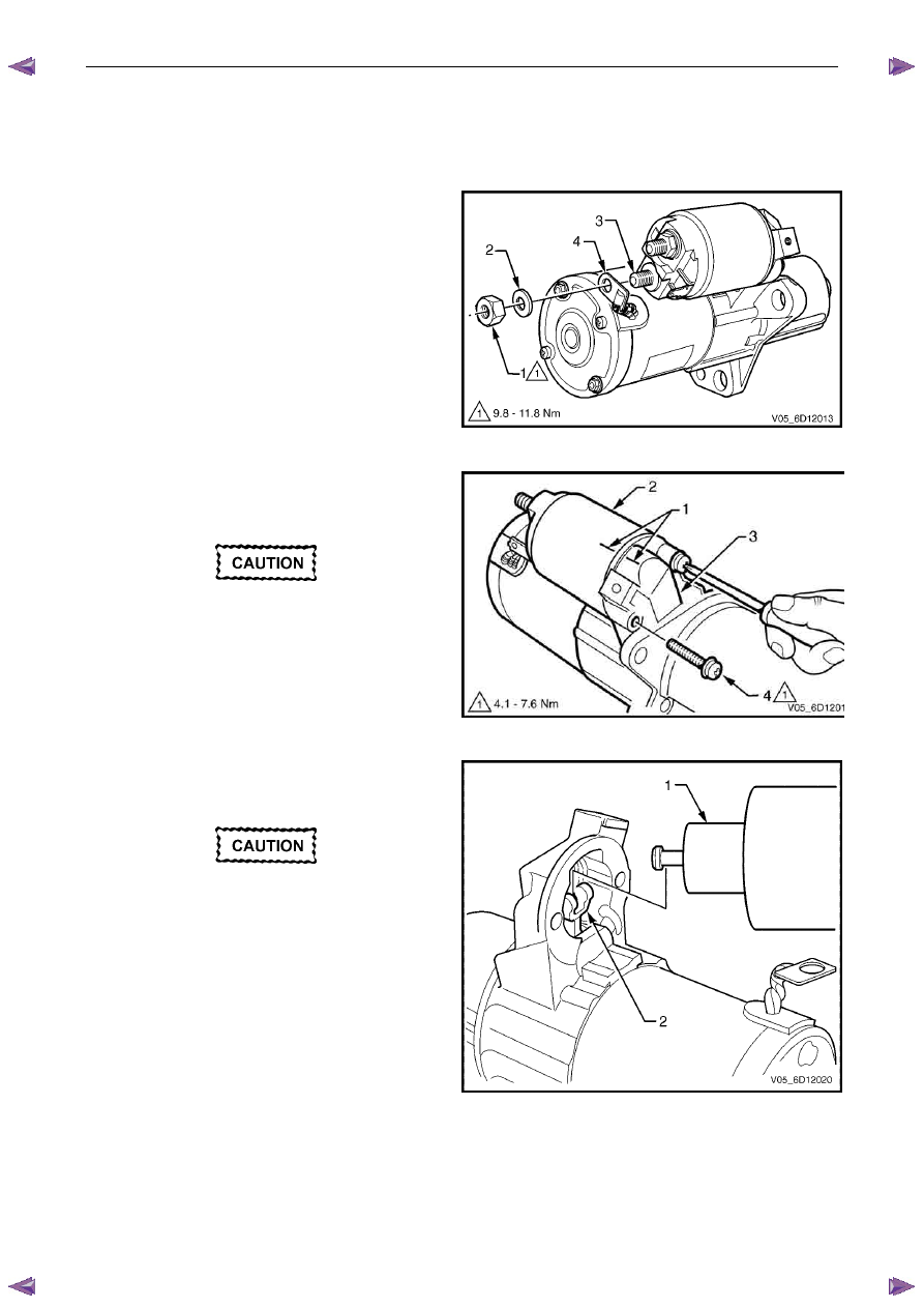
1
Clamp the starter motor, by the mounting lug in the
drive-end housing, in a vice with soft jaws.
2
Remove the nut (1) and washer (2) from the
solenoid switch M terminal (3).
3
Remove the braided cable (4) from the M terminal.
Figure 6D1-2 – 19
4
Scribe aligning marks (1) on the drive-end
housing (2) and the solenoid switch housing (3) to
aid reassembly.
When using an impact driver, avoid
damaging the drive-end housing or
rounding the screw slots of the solenoid
switch mounting screws.
5
Remove the two solenoid switch mounting
screws (4). It may be necessary to loosen the
mounting screws using an impact driver.
Figure 6D1-2 – 20
6
Remove the solenoid switch from the drive-end
housing.
Do not lose the plunger return spring.
7
Unhook and remove the solenoid switch plunger (1)
from the drive assembly fork lever (2).
Figure 6D1-2 – 21
Starting System – V6
Page 6D1-2–26
Reassemble
1
Reassemble the solenoid in the reverse order of the disassembly procedure noting the following points.
Dry all parts thoroughly before assembly,
taking care not to breathe in any vapours.
2
Lightly coat the solenoid switch plunger with 10% molybdenum disulphide grease.
Excess grease can enter the contact chamber
of the solenoid switch and cause contact
problems. Do not use too much grease.
3
Hook the plunger over the fork lever.
4
Insert the return spring into the plunger.
5
Slide solenoid switch over the plunger.
6
Align the solenoid switch with drive-end housing ensuring the solenoid switch terminal P – 4 faces away from the
pole housing.
7
Install and tighten the solenoid switch mounting screws.
Solenoid switch mounting screw
torque specification . . . . . . . . . .4.1 – 7.6 Nm
8
With the starter motor reassembled, perform a No Load Test, refer to 4.3 Starter Motor Bench Tests.
9
If the starter motor fails the No Load Test specification, replace the starter motor.
4.5
Solenoid Switch Tests
Test the Solenoid Switch
1
Inspect the solenoid switch for any external
damage.
2
Replace the solenoid switch if it displays
significant damage.
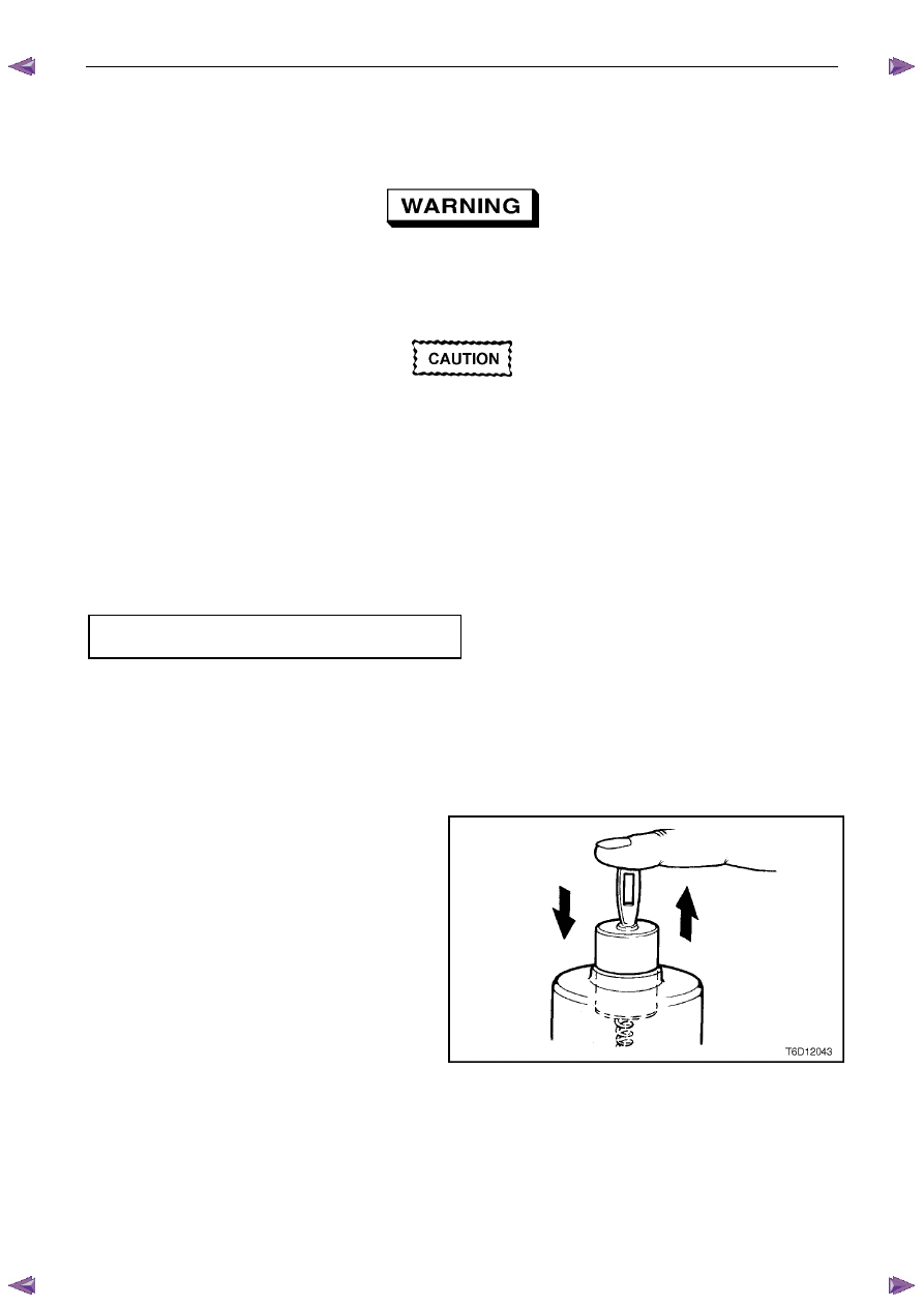
3
Install the return spring and plunger into the
solenoid switch.
4
Check the movement of the plunger, as follows:
a
Depress the plunger fully.
b
Release the plunger.
c
If the plunger sticks or binds in the switch
bore, clean or replace the solenoid switch
assembly as required.
Figure 6D1-2 – 22
Starting System – V6
Page 6D1-2–27
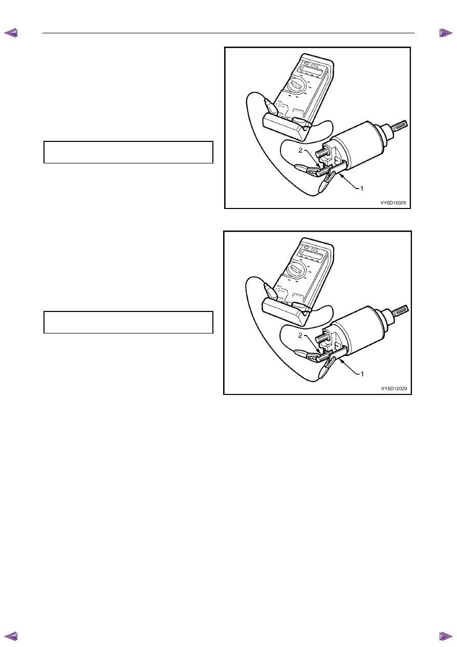
5
Connect a multimeter set to measure resistance
between the solenoid switch M terminal (1) and
the solenoid switch terminal P – 3 (2).
6
Record the resistance reading.
7
Replace the solenoid switch if the resistance is
outside the specification.
Pull-in winding
resistance @ 20
°C. . . . . . . . 0.33 – 0.37 Ω
Figure 6D1-2 – 23
8
Connect a multimeter set to measure resistance
between the solenoid switch housing (1) and the
solenoid switch terminal P – 3 (2).
9
Replace the solenoid switch if the resistance is
outside the specification.
Hold-in winding
resistance @ 20
°. . . . . . . . ..0.75 – 0.87 Ω
Figure 6D1-2 – 24
Нет комментариевНе стесняйтесь поделиться с нами вашим ценным мнением.
Текст