Isuzu KB P190. Manual — part 1326
8A-366 ELECTRICAL-BODY AND CHASSIS
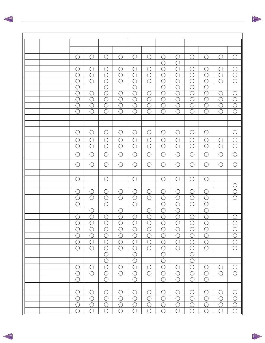
Connector No. B23
SOUTH
AFRICA
SAUDI
ARABIA
ISRAEL EUROPE
OTHER
Terminal Connector
place
4JJ1-TC HFV6 4JA1T(L)
HFV6
4JJ1-TC
HFV6
RHD
LHD
G.EXP
RHD
4JJ1-TC
C24SE
AUSTRALIA
HFV6
AUSTRALIA
1
Power ground
2
Cruise main
―
―
―
―
―
―
―
―
―
―
3
Charge
4
Brake
5
ABS control unit
6
Fuel consumption
―
―
―
―
―
7
Tachometer pulse
8
Speedometer pulse
9
Rheostat
10
Taillight relay
11
―
―
―
―
―
―
―
―
―
―
―
―
―
12
―
―
―
―
―
―
―
―
―
―
―
―
―
13
Ambient
temperature sensor
―
14
Seat belt
15
Key remind switch
16
Engine coolant
temperature sensor
17
Fuel gauge unit and
sender
18
Fuel level
―
―
―
―
―
―
―
―
―
―
―
―
19
Sedimenter
―
―
―
―
―
20
Door ajar
―
―
―
―
―
―
―
―
―
―
―
21
Power drive
―
22
3rd start
―
23
Fuel filter
―
―
―
―
―
24
Cruise set
―
―
―
―
―
―
25
Check trans
―
26
SVS
―
27
4WD
―
28
4WD - L
―
29
A/T oil temperature
―
30
Check 4WD
―
31
CAN (+)
―
―
―
―
―
―
―
―
32
CAN (-)
―
―
―
―
―
―
―
―
33
Turn signal - LH
34
ABS
35
Glow
―
―
―
―
―
36
―
―
―
―
―
―
―
―
―
―
―
―
―
37
Hi – beam (+)
38
Check engine
39
Oil pressure
40
SRS control unit
ELECTRICAL-BODY AND CHASSIS 8A-367
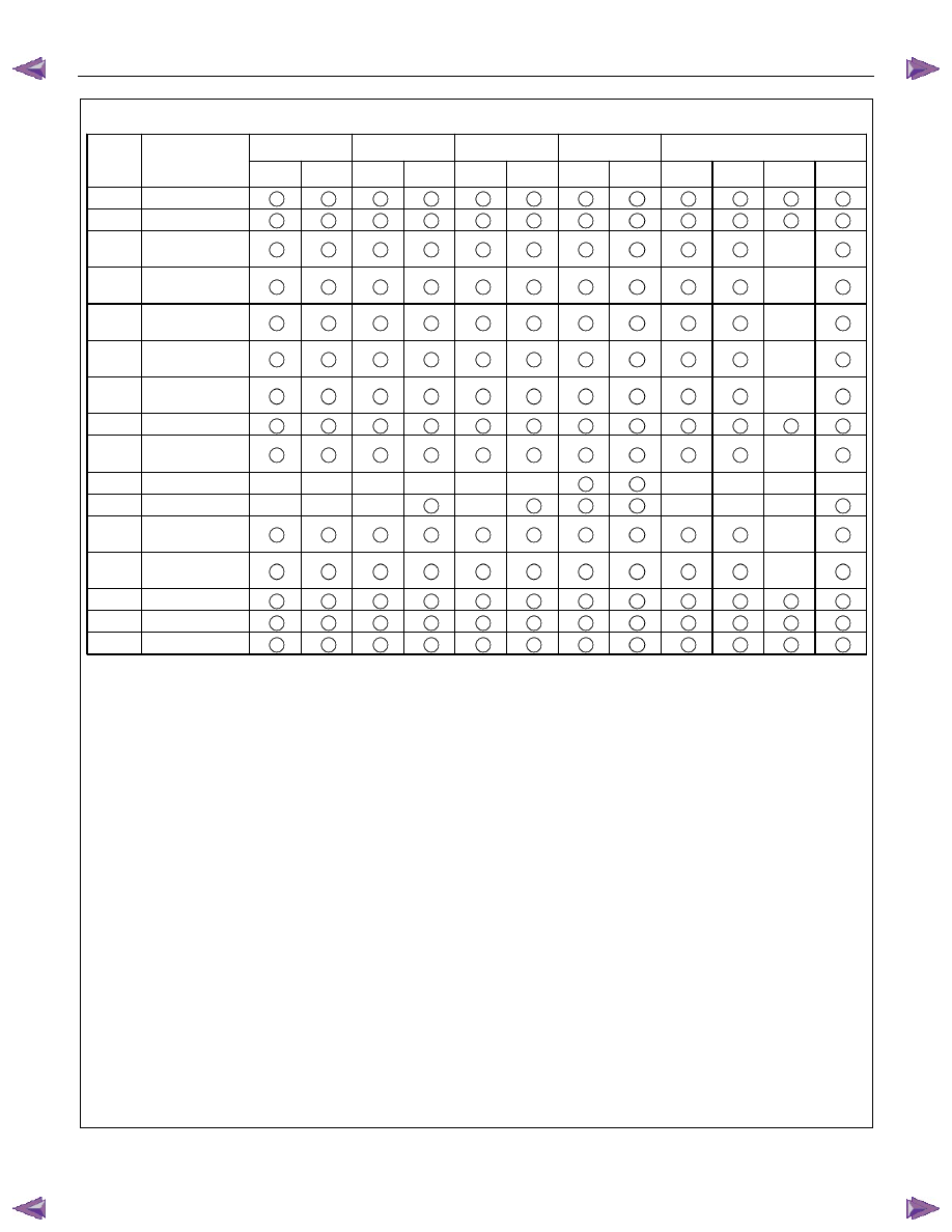
Connector No. B24
SOUTH
AFRICA
SAUDI
ARABIA
ISRAEL EUROPE
OTHER
Terminal Connector
place
4JJ1-TC HFV6 4JA1T(L)
HFV6
4JJ1-TC
HFV6
RHD
LHD
G.EXP
RHD
4JJ1-TC
C24SE
AUSTRALIA
HFV6
AUSTRALIA
1 Signal
ground
2 SRS
ground
3
A/T shift indicator
“3”
―
4
A/T shift indicator
“D”
―
5
A/T shift indicator
“N”
―
6
A/T shift indicator
“R”
―
7
A/T shift indicator
“P”
―
8 Ignition
9 Ambient
temperature sensor
―
10
RR fog light
―
―
―
―
―
―
―
―
―
―
11
FRT fog light
―
―
―
―
―
―
―
12
A/T shift indicator
“2”
―
13
A/T shift indicator
“L”
―
14
Turn signal - RH
15
Door SW - driver
16 Power
source
8A-368 ELECTRICAL-BODY AND CHASSIS
140R300007
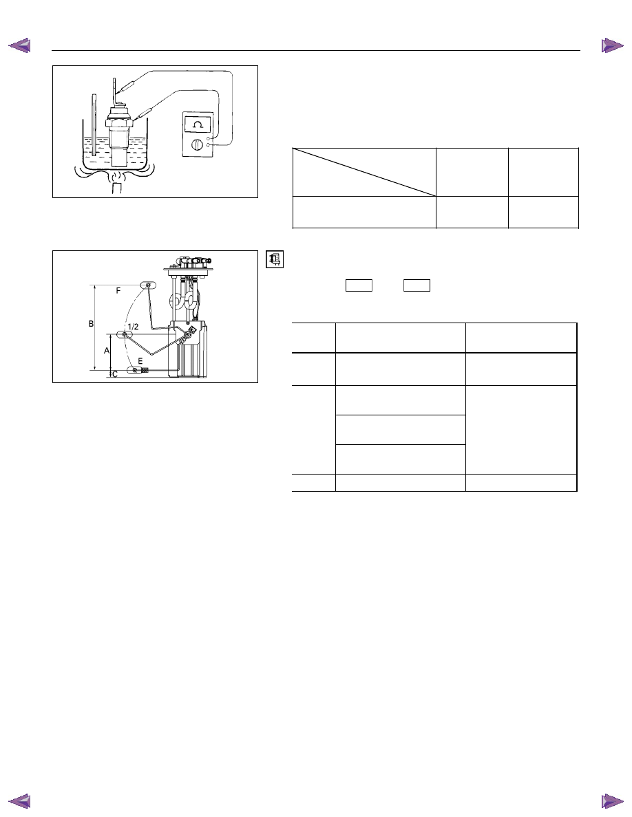
Thermo Unit Inspection
INSPECTION
Use a circuit tester to measure the thermo unit resistance.
Replace the unit when the result of inspection is found
abnormal.
Temperature
Check
condition
60
°C
(140
°F)
115
°C
(239
°F)
Resistance
value (
Ω)
168
±3.5
+2.5
30.9
–2.0
041R300002
Fuel Gauge Unit Inspection
Measure the fuel gauge unit resistance between the connector
terminals 2
F2
and 3
F2
while shifting the float from “E”
to “F” point.
Fuel Tank Resistance
Level
Float position
mm
Standard resistance
Ω
F (B)
217.5
+2.2
17
–0.8
106.6
(4JJ1-TC/4JK1-TC)
105.1
(C24SE, 4JA1T(L))
1/2 (A)
112.8
(4JH1-TC)
45
± 4.5
E (C)
16.2 120
± 2.0
ELECTRICAL-BODY AND CHASSIS 8A-369
Low Fuel Indicator Light
1. Disconnect the fuel gauge unit wire connector.
2. Turn the key switch on. Check that the bulb lights.
If operation is not correct, remove and check the bulb or circuit.
or If check whether low fuel turns on fuel input (B-24) at the
time of open and key on.
∗ meter is check at low fuel
RTW78ASH001501
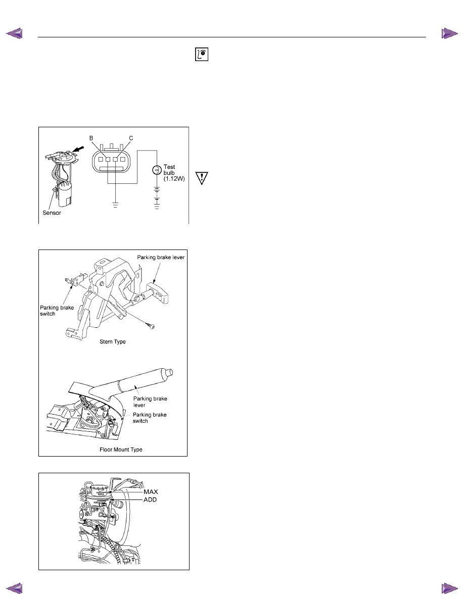
Check level sensor operation
1. Remove the fuel gauge unit.
2. Apply battery voltage between terminal (B) and (C) through
a 1.12 watt bulb. Check that the bulb lights.
Note:
It will take a short time for the bulb light.
3. Submerge the sensor in fuel. Check that the bulb goes out.
If operation is not correct, replace the fuel tank unit.
BRAKE SYSTEM WARNING LIGHT
The brake system warning light comes on while the parking
brake is set and the engine run position.
RTW48AMH000101
Note:
The parking brake indicator light circuit is designed to
prevent driving of the vehicle with the parking brake on.
It does not indicate the condition of the parking brake
system.
The parking brake switch is in parallel with the brake fluid
switch.
The brake system warning light also comes on when reservoir
brake fluid level falls below the specified limit with the parking
brake released and the engine run position.
Нет комментариевНе стесняйтесь поделиться с нами вашим ценным мнением.
Текст