Isuzu KB P190. Manual — part 1325
8A-362 ELECTRICAL-BODY AND CHASSIS
Tachometer Off-Vehicle Inspection
Remove the tachometer from the meter assembly and
measure the resistance value and the current consumption
between each terminal.
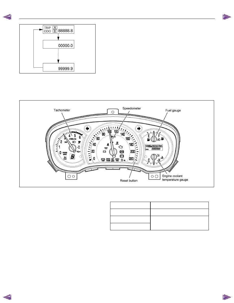
SELF DIAGNOSTIC FUNCTION
Check that the speedometer, tachometer, fuel gauge, and
temperature gauge operate properly.
821R300033
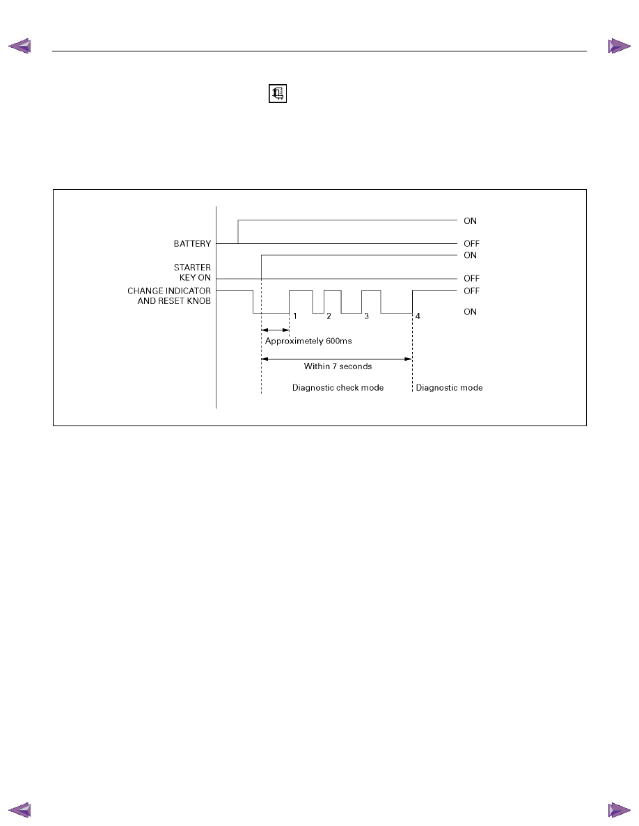
Entering the self-diagnostic mode
1. Push in and hold the “Change Indicator and Reset” knob.
2. Turn the ignition ON.
3. When the LCD odometer turns ON, release the “Change
Indicator and Reset” knob.
4. Push in and release the “Change Indicator and Reset” knob
three times in quick succession.
The meter cluster is now in “Self-diagnostic” mode.
NOTE: Steps 2-4 must be performed within 7 seconds.
The meter cluster will not enter “Self-diagnostic” mode if any of
the following conditions occur:
1. The “Change Indicator and Reset” knob is not depressed
when the ignition is turned ON.
2. The “Change Indicator and Reset” knob is released within
600ms of turning the ignition ON.
3. The “Change Indicator and Reset” knob is not depressed
and released three times within 7 seconds.
ELECTRICAL-BODY AND CHASSIS 8A-363
Self –diagnostic mode
LCD condition
• All LCDs are lit during the transition from self-diagnostic
decision mode to self-diagnostic mode
• The odometer/trip indicator scrolls throng its entire range
approximately once every 600 ms. All digits are lit (segment
check indication). This continues until the self-diagnostic
mode is terminated.
Meter and gauge indications
Meter and gauge indications with the change indicator and
reset knob on (self-diagnostic mode) are as shown in the
following table.
RTW78ASF000101
Speedometer
100 kilometers per hour
Tachometer 3,000
rpm
Fuel gauge
Temperature gauge
Mid-point on the dial
All indications return to zero when the change indicator and
reset knob is turned off.
The self-diagnostic mode and the self-diagnostic decision
mode are cancelled when the ignition switch is turned to the
OFF position. They also cancel when a speed pulse is sensed.
If either of the self-diagnostic modes are cancelled by turning
the ignition switch to the OFF position, the diagnostic unit
remains in the stand-by condition.
If cancellation occurs when a speed pulse is sensed, the unit
remains in the ordinary operating condition.
8A-364 ELECTRICAL-BODY AND CHASSIS
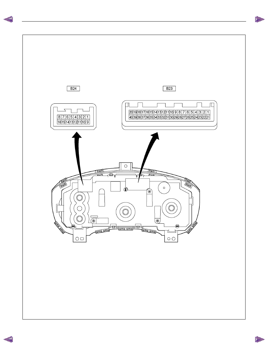
Meter connector pin arrangement
RTW780XF007401
ELECTRICAL-BODY AND CHASSIS 8A-365
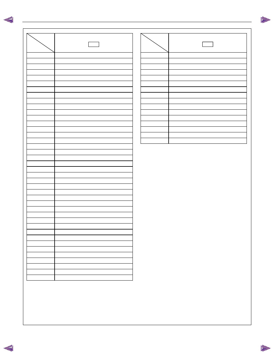
Connector
Ter-
No.
minal No.
B23
1 Power
ground
2 Cruise
main
3 Charge
4 Brake
5
ABS control unit
6 Fuel
consumption
7 Tachometer
pulse
8 Speedometer
pulse
9 Rheostat
10 Taillight
relay
11 -
12 -
13
Ambient temperature sensor
14 Seat
belt
15
Key remind switch
16
Engine coolant temperature sensor
17
Fuel gauge unit and sender
18 Fuel
level
19 Sedimenter
20 Door
ajar
21 Power
drive
22 3rd
start
23 Fuel
filter
24 Cruise
set
25 Check
trans
26 SVS
27 4WD
28
4WD - L
29
A/T oil temperature
30 Check
4WD
31 CAN
(+)
32 CAN
(-)
33
Turn signal - LH
34 ABS
35 Glow
36 -
37
Hi – beam (+)
38 Check
engine
39 Oil
pressure
40
SRS control unit
Connector
Ter-
No.
minal No.
B24
1 Signal
ground
2 SRS
ground
3
A/T shift indicator “3”
4
A/T shift indicator “D”
5
A/T shift indicator “N”
6
A/T shift indicator “R”
7
A/T shift indicator “P”
8 Ignition
9
Ambient temperature sensor
10
RR fog light
11
FRT fog light
12
A/T shift indicator “2”
13
A/T shift indicator “L”
14
Turn signal - RH
15
Door SW - driver
16 Power
source
Нет комментариевНе стесняйтесь поделиться с нами вашим ценным мнением.
Текст