Isuzu KB P190. Manual — part 253
ENGINE ELECTRICAL 6D – 11
RTW46DSH000301
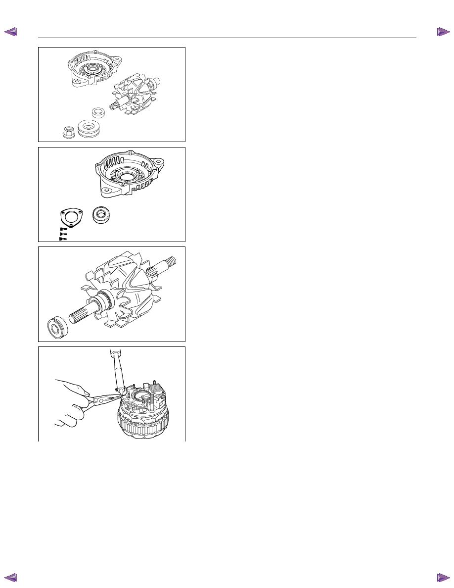
7. Rotor
Assembly
1. Remove the rotor from front cover assembly.
Remove the front cover stator and rectifier.
RTW46DSH000701
8. Front Cover Assembly
1. Remove the front cover bearing retainer screws.
2. Remove the bearing.
RTW46DSH000801
9. Rear rotor bearing
• Re-use improper parts.
10. Rectifier
1. Disconnect the stator coil leads between each rectifier
by melting the solder connection.
Hold the lead wire between the solder and the rectifier
with a pair of long nose pliers.
This will prevent heat transfer and resultant damage to
the rectifier.
RTW46DSH000401
6D – 12 ENGINE ELECTRICAL
INSPECTION AND REPAIR
Make the necessary adjustments, repairs, and part replacement if excessive wear or damage is discovered during
inspection.
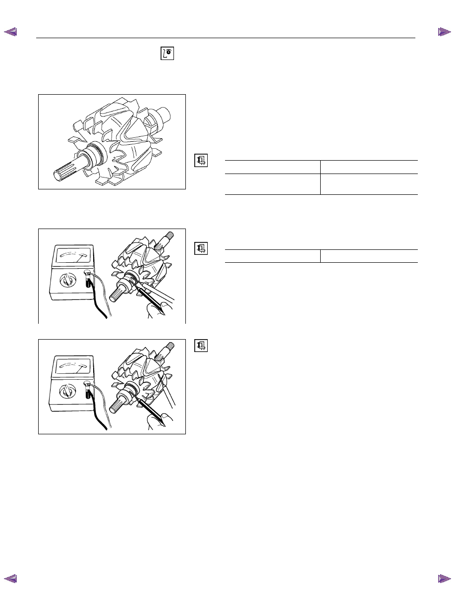
ROTOR ASSEMBLY
1. Inspect the slip ring faces for dirt and pitting.
Wipe away any dirt with a clean cloth soaked in
alcohol.
2. Measure the slip ring diameter.
Slip Ring Diameter
mm (in)
Standard Limit
RTW06DSH000101
31.6 (1.245)
30.6 (1.183)
If the slip ring diameter is less than the specified limit, the
slip rings must be replaced.
3. Measure the rotor coil resistance.
Rotor Coil Resistance at 20
°C (68°F) ohms
Standard 3.8
RTW46DSH001001
RTW46DSH001101
4. Check for continuity between the slip rings and the
rotor core or shaft.
If there is continuity, the entire rotor assmbly must be
replaced.
ENGINE ELECTRICAL 6D – 13
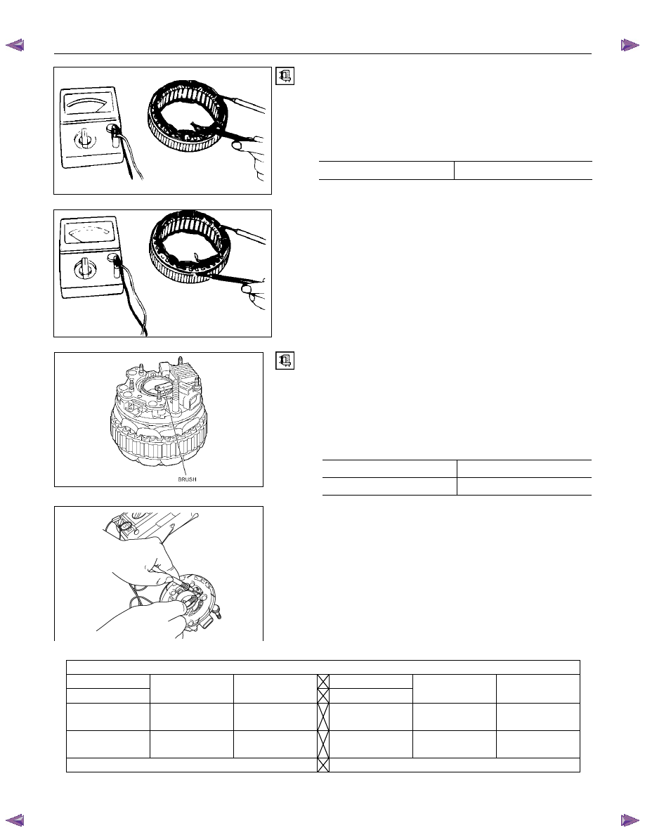
STATOR COIL ASSEMBLY
1. Check for continuity across the stator coils.
If there is no continuity, the stator coils must be
replaced.
Resistance Between The Terminal “N” and the Coil Ends
(Reference) ohms
Standard 0.1
066RY00022
2. Check for continuity between each stator coils and the
stator core.
If there is continuity, the stator coils must be replaced.
066RY00023
RTW46DSH004801
BRUSH
Measure the length of the brush. If abrasion has reduced
the brush length to less than 6.5 mm, the brush must be
replaced with a new one.
A wear line is inscribed in the brush. If the line is not
visible, the brush must be replaced.
Brush Length (Reference)
mm (in)
Standard Limit
25 (1.0)
6.5 (0.25)
RTW46DSH001201
Rectifier
Tester wire
E BAT
U, V, and WN
⊕
U, V, and WN
⊕
⊕
----- Conductivity
⊕
-----
No
conductivity
No
conductivity
-----
Conductivity -----
Negative
side diode check
Positive
side diode check
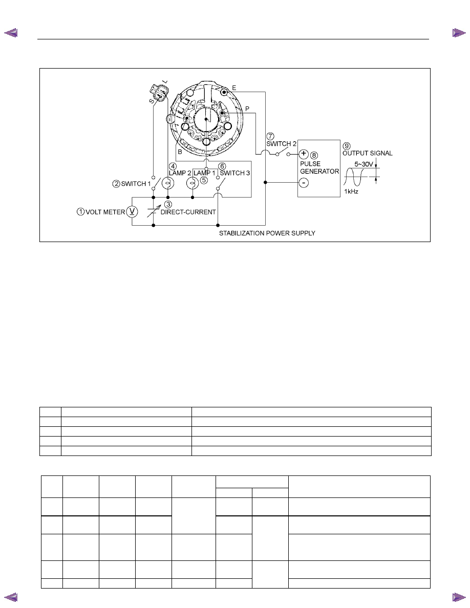
6D – 14 ENGINE ELECTRICAL
RECTIFIER ASSEMBLY
RTW46DSF000301
1. Voltmeter
2. Switch
1
3. DC regulated power supply
4. Lamp
2
5. Lamp
1
6. Switch
3
7. Switch
2
8. Pulse
generator
9. Output
signal
Test circuit
Refer to the judgment criteria shown in the Table below.
Carefully check Items 1~5. If all the items are OK, the IC
regulator is normal.
Circuit components
1
DC regulated power supply
0~20 volts variable with output of 1 ampere or more
2
Lamps (2)
12 volts, 1.4~3.4 watts
3
Switches (3)
-----
4
DC voltmeter
0~30 volts, 0.5 grade
5
Pulse generator (Oscillator)
5~30 volt output at a frequency of 1kHz
Judgment criteria
Lamp condition
No.
Switch
1
Switch
2
Switch
3
Voltmeter
reading
Lamp 1
Lamp 2
Remarks
1
ON OFF OFF
On
(dim)
ON
Initial excitation check
2
ON ON OFF
12V
On or
flashing
Full excitation check
3
ON ON OFF 16V
Off or
on (dim)
OFF
Lamp 1 off or dimly lit when the
voltmeter shows less than 12 volts or
16 volts
4
OFF ON OFF 12V
On or
flashing
Stator and brush separation check
5
ON ON ON 18V On
ON
Excess voltage check
Нет комментариевНе стесняйтесь поделиться с нами вашим ценным мнением.
Текст