Isuzu KB P190. Manual — part 252
ENGINE ELECTRICAL 6D – 7
GENERATOR
REMOVAL AND INSTALLATION
Read this Section carefully before performing any removal and installation procedure. This Section gives you
important points as well as the order of operation. Be sure that you understand everything in this Section before you
begin.
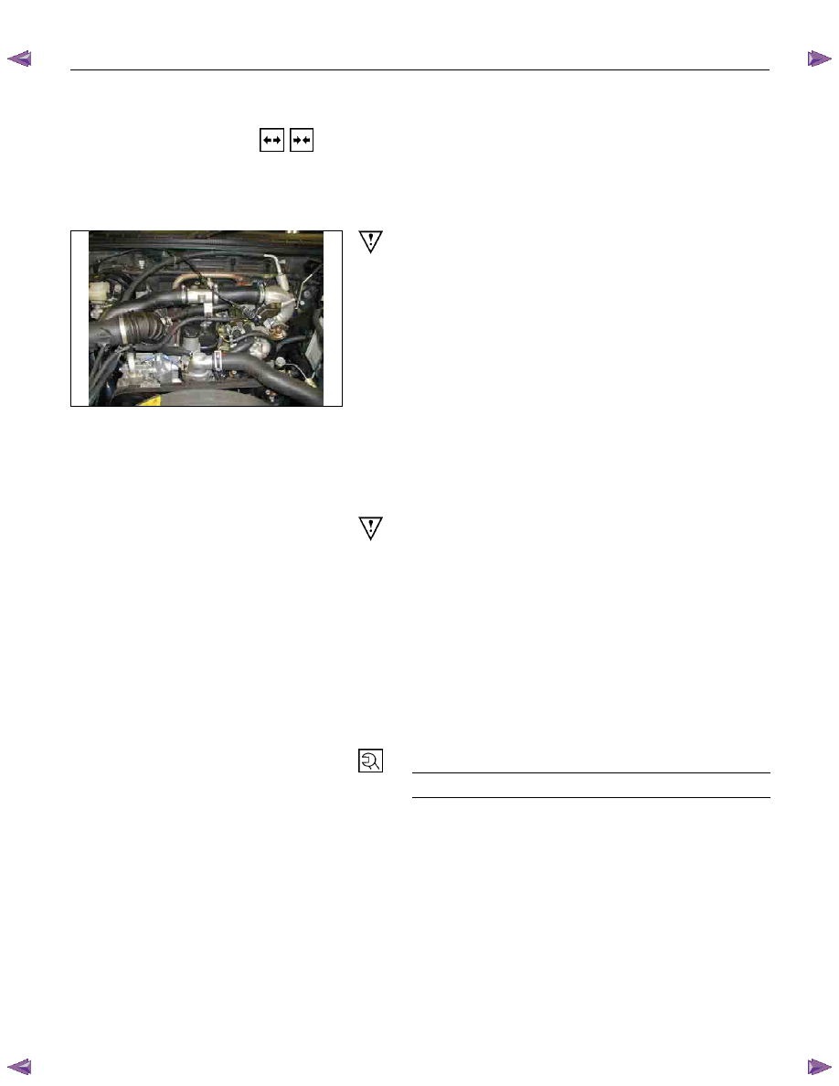
P1010002
Important Operations-Removal
Cooling Fan Belt
1. Disconnect the battery cables at the battery terminals.
2. Loosen and remove the fan belt adjusting plate bolts.
3. Remove the fan belt from the generator drive pulley.
Generator
1. Remove the vacuum pump hose.
2. Remove the generator bolt and the generator from the
bracket.
Important Operations-Installation
Follow the removal procedure in the reverse order to
perform the installation procedure. Pay careful attention to
the important points during the installation procedure.
Generator
1. Install the generator to the bracket.
2. Tighten the generator bolt to the specified torque.
3. Install the vacuum pump hose.
Generator Bolt Torque
N
m (kgm/Ibft)
40 (4.1/30)
6D – 8 ENGINE ELECTRICAL
033RY00009
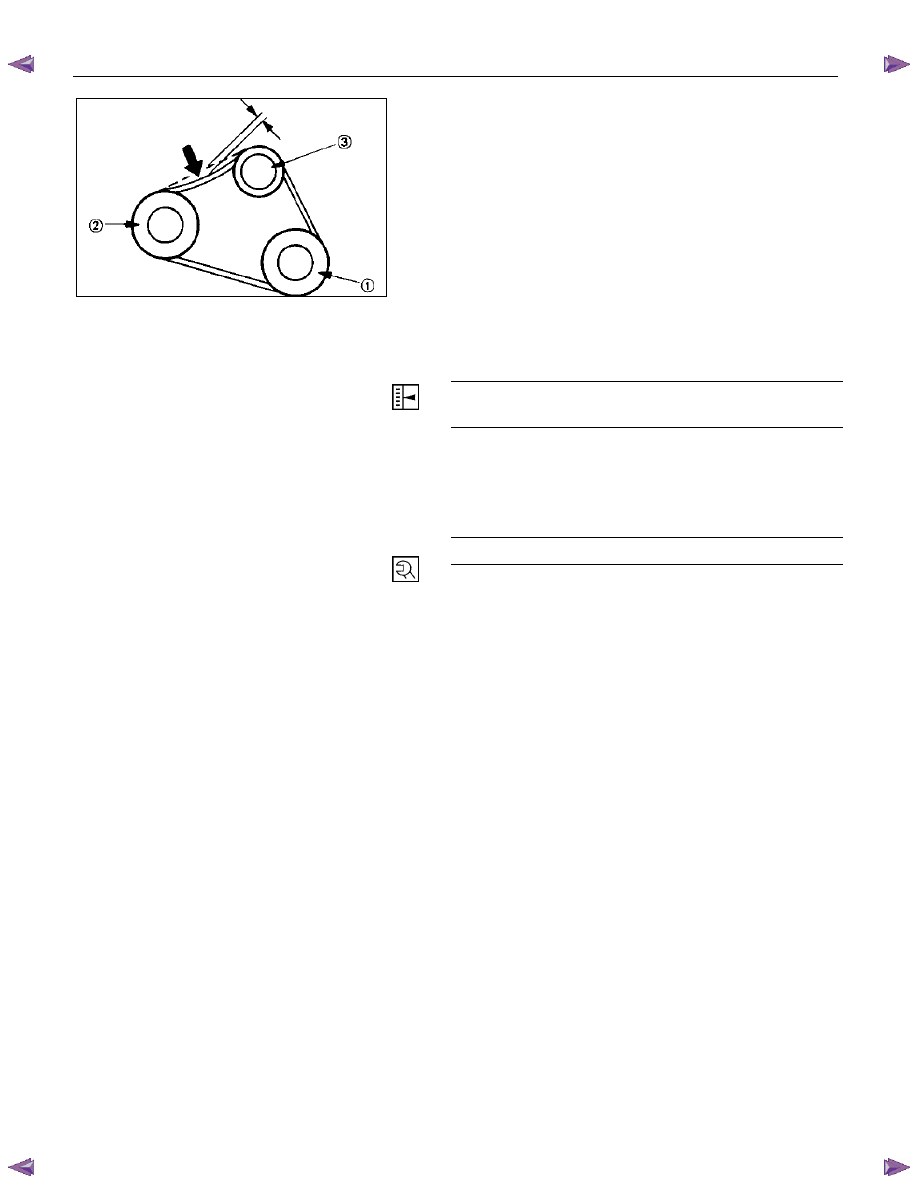
Cooling Fan Drive Belt
1. Hold the generator toward the engine.
2. Install the fan belt to the three pulleys.
1 Crankshaft
pulley
2 Generator
pulley
3
Cooling fan drive pulley
3. Adjust the fan belt tension
Fan belt tension is adjusted by moving the generator.
Depress the drive belt mid-portion with a 98N (10
kg/22 Ib) force.
Cooling Fan Drive Belt Deflection
mm (in)
New belt 4 - 7 (0.16 - 0.28)
Reuse belt 6 - 9 (0.24 - 0.35)
4. Tighten the adjusting plate bolts to the specified
torque.
Adjusting Plate Bolt
N·m (kg·m/lb·ft)
19 (1.9/14)
5. Reconnect the battery cable to the battery.
ENGINE ELECTRICAL 6D – 9
DISASSEMBLY
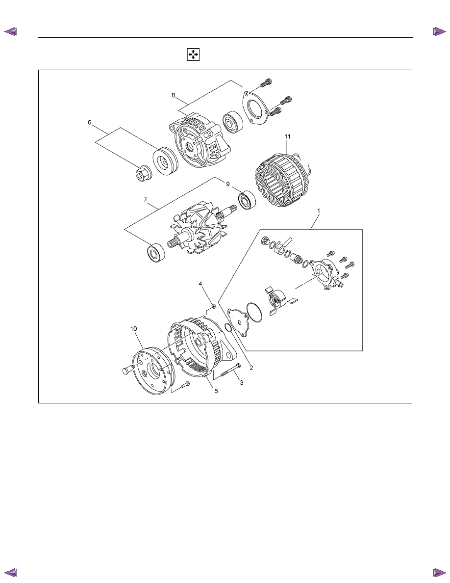
RTW46DLF000401
Disassembly Step
1. Vacuum pump
2. O-ring
3. Through bolt
4. B Terminal nut
5. Rear cover
6. Pulley
7. Rotor assembly
8. Front cover assembly
9. Rear rotor bearing
10. Rectifier assembly
11. Stator assembly
12. Rotor assembly
6D – 10 ENGINE ELECTRICAL
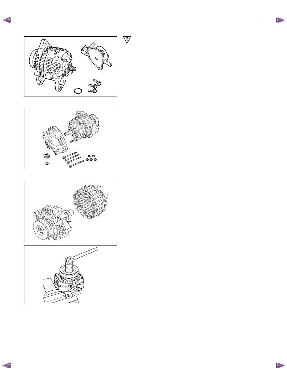
RTW46DSH000101
Important Operations
1. Vacuum
Pump
1. Loosen the vacuum pump fixing screws.
2. Support the vacuum pump O-ring.
3. Carefully remove the O-ring.
2. Cover
RTW46DSH000201
3. Through
Bolt
1. Remove the M5 through bolt.
2. Separate the front and rear sides of the vacuum pump.
3. Insert the tips of 2 ordinary screwdrivers into the space
between the front cover and the stator core. Remove
the front cover and rotor together with the rear cover
and stator.
If removal is difficult, push the rear cover to the side and
lightly tap the end of the shaft with a plastic hammer to
loosen it.
• The front cover oil seal must be replaced with a new
one when the front cover is removed.
• Take care not to damage the stator core with the
screwdriver tips.
RTW46DSH000601
RTW46DSH002101
4. Pulley
1. Carefully clamp the rotor assembly in a vise.
2. Loosen the pulley nut.
3. Remove the pulley and the front cover from the rotor.
Нет комментариевНе стесняйтесь поделиться с нами вашим ценным мнением.
Текст