Isuzu KB P190. Manual — part 254
ENGINE ELECTRICAL 6D – 15
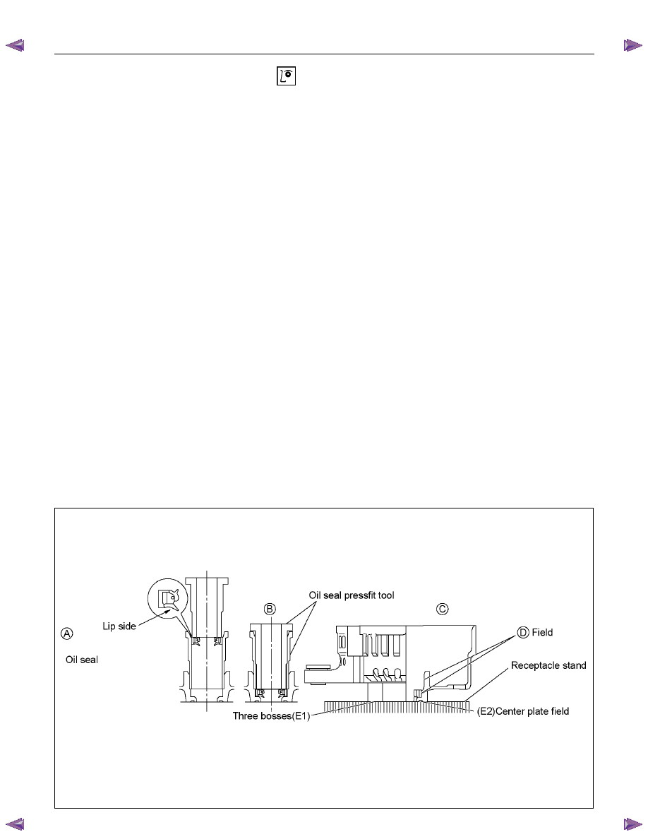
Oil seal
The oil seal must be replaced with a new one whenever
the alternator is disassembled.
Oil Seal Replacement
1. Push the old oil seal from the rear bracket outside
holes.
2. Use the insertion tool to press the new oil seal into
place. Follow the procedure shown in Figures A, B, C
and D.
Position the oil seal beneath the shaft and the
guide lip.
Position the cradle against the rear cover bosses
(3 points) so that the E1 and E2 surfaces fit into
the cradle. Take care not to damage the E1 and
E2 surfaces.
After completing the procedure, carefully check the
oil seal seating. Be absolutely sure that the seal is
evenly inserted (no warp) and level with the
surrounding surfaces.
Caution
Be sure that no foreign material enters the space
between the oil seal and the rotor shaft surfaces
during the installation procedure.
Take care not to damage the D surface.
Under no circumstances may the original oil seal
be reused.
The oil seal must be perfectly flat after being
pressed into place. If the oil seal is tilted, there will
be oil leakage.
RTW46DSF000101
6D – 16 ENGINE ELECTRICAL
RTW46DSH000901
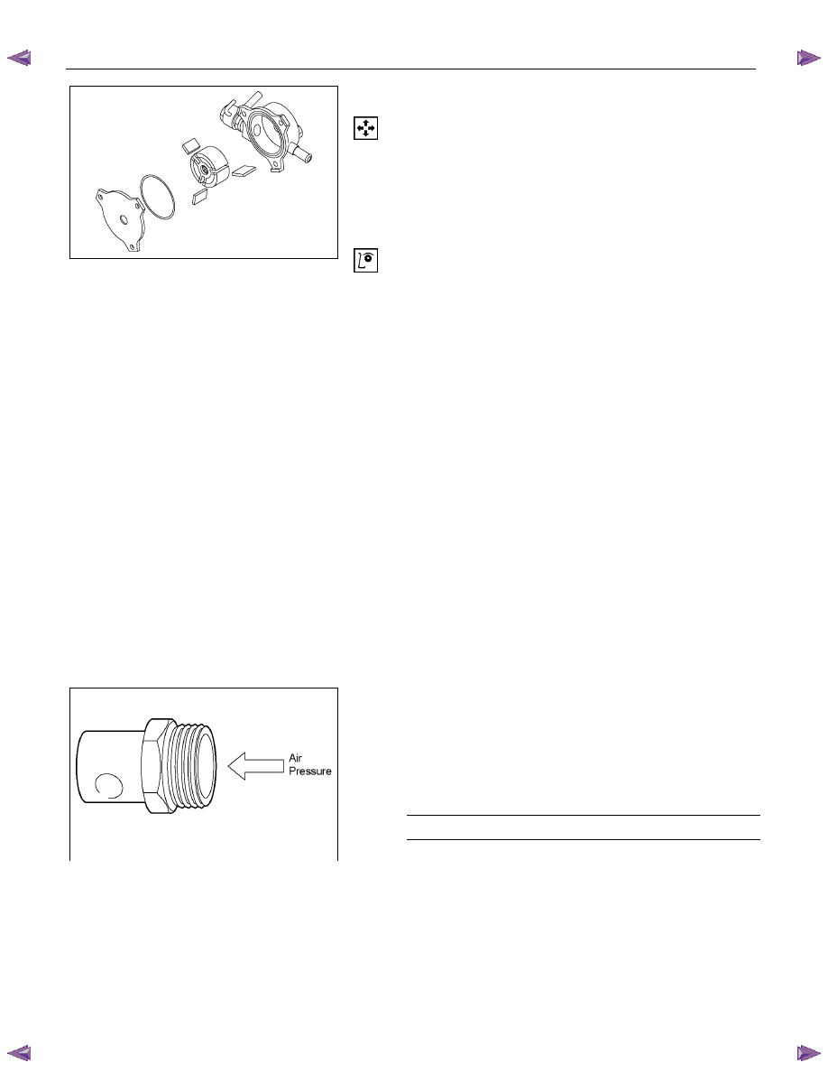
Vacuum Pump
Vacuum Pump Disassembly
1. Remove the center plate from the vacuum pump
housing.
2. Remove the vacuum pump rotor and the vanes from
the housing.
Inspection
Vacuum Pump Housing and Center Plate
Inspect the vacuum pump housing and the center plate for
excessive wear, abrasion, and scoring.
If any of these conditions are present, the vacuum pump
housing and center plate must be replaced.
Vane
Inspect the vanes for excessive wear and damage.
Replace all four vanes if either of these conditions are
present.
Never replace only one vane.
Rotor
1. Inspect the rotor for excessive wear, abrasion, and
scoring.
Pay particular attention to the internal spline.
Replace the rotor if any of these conditions are
present.
2. Inspect the generator rotor shaft splines for backlash.
Replace the rotor if backlash is present.
RTW46DSH005201
Check Value
1. Carefully force the valve from the “B” side as shown in
the illustration.
The valve must move smoothly.
If it does not, the check valve must be replaced.
2. Apply compressed air to the “A” side.
Air Pressure
kPa (kg/cm
2
/psi)
98 - 490 (1-5/14 – 71)
Check for air leakage from the check valve.
If there is air leakage, the valve must be replaced.
ENGINE ELECTRICAL 6D – 17
RTW46DSH001801
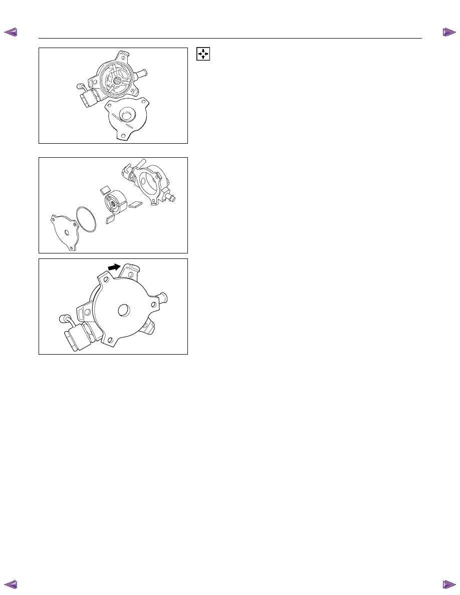
Vacuum Pump Reassembly
1. Install the vanes to the rotor slits.
The rounded side of the vanes must be facing the
rotor housing.
RTW46DSH001901
2. Install the rotor with the concave side facing the center
plate.
RTW46DSH002001
3. Install the center plate to the rotor housing.
Be sure to use a new O-ring.
6D – 18 ENGINE ELECTRICAL
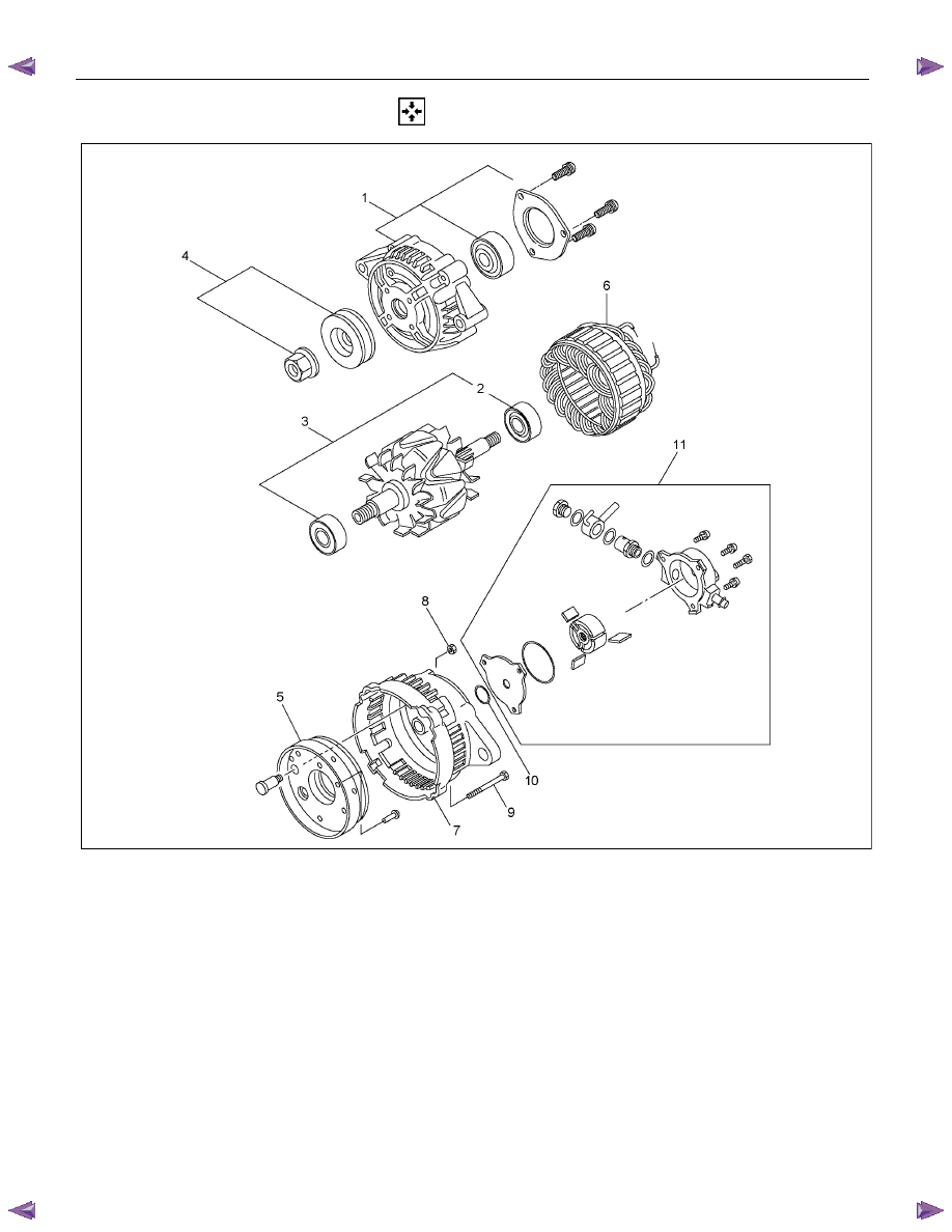
REASSEMBLY
RTW46DLF000501
Reassembly Step
1. Front cover
2. Rear rotor bearing
3. Rotor Assembly
4. Pulley
5. Rectifier Assembly
6. Stator Assembly
7. Rear cover
8. B Terminal nuts
9. Through bolt
10. O-ring
11. Vacuum pump
Нет комментариевНе стесняйтесь поделиться с нами вашим ценным мнением.
Текст