Isuzu KB P190. Manual — part 892

Engine Management – V6 – Service Operations
Page 6C1-3–44
3
Disconnect the wiring harness connector (1) from the
knock sensor (2).
Figure 6C1-3 – 59
4
Remove the bolt (1) attaching the knock sensor (2) to
the engine block, and remove the knock sensor.
Figure 6C1-3 – 60
Reinstall
Reinstallation of the knock sensor is the reverse of the removal procedure, noting the following:
1
Ensure the knock sensor mounting surface is flat and free of any dirt, oxidisation, etc.
Engine Management – V6 – Service Operations
Page 6C1-3–45
Ensure the knock sensor is fully seated
before tightening the attaching bolt.
Do not over-tighten the attaching bolt as
incorrect operation of the knock sensor may
result.
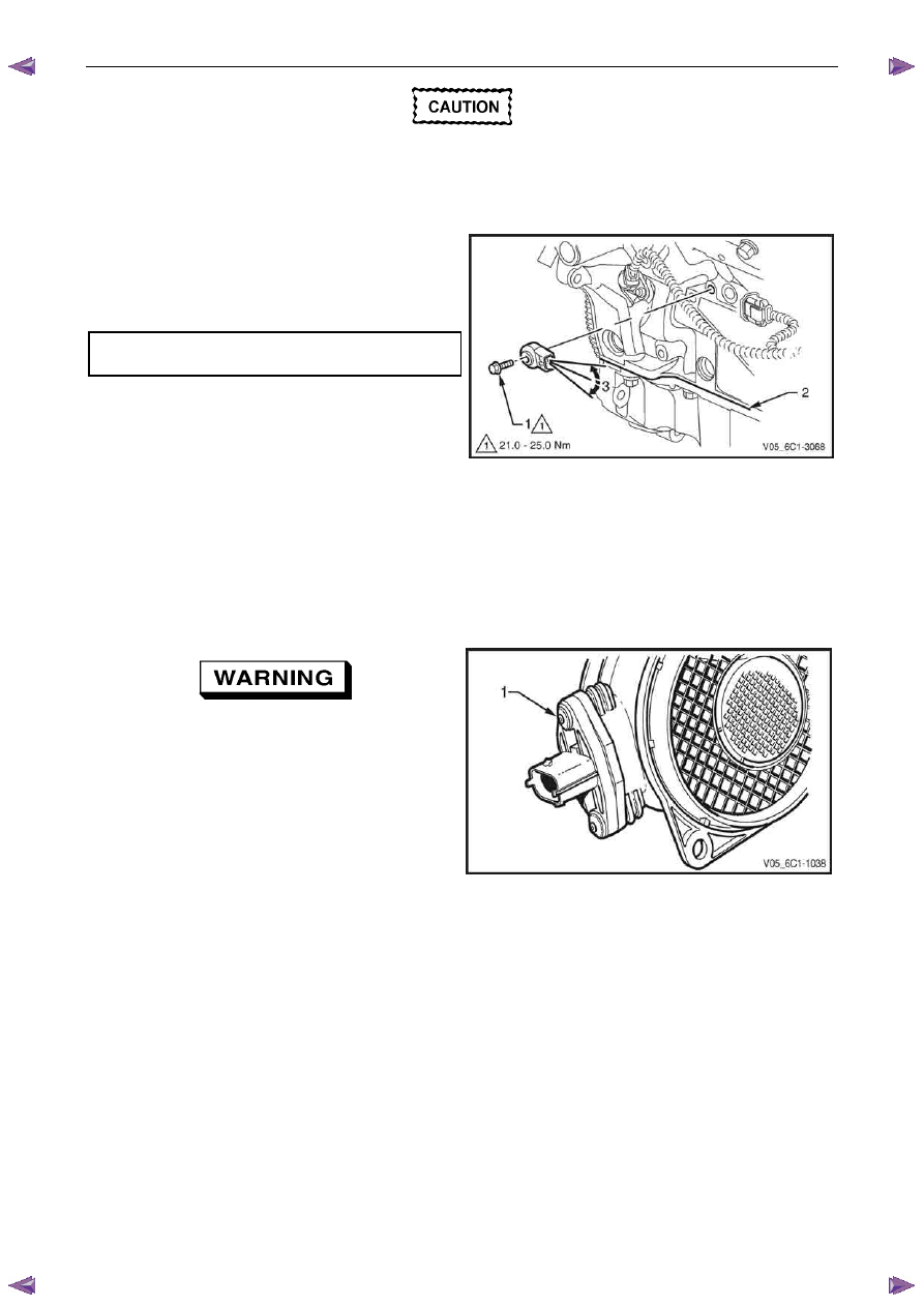
2
Reinstall the knock sensor and bolt (1). Align the
knock sensor so that it is parallel to the engine oil pan
mounting surface (2), ± 3° (3).
3
Tighten the knock sensor bolt to the correct torque
specification.
Knock sensor attaching bolt
torque specification . . . . . . . . .21.0 – 25.0 Nm
4
Road test the vehicle and check for correct operation.
Figure 6C1-3 – 61
2.20 Mass Air Flow Sensor
The intake air temperature (IAT) sensor is part of the mass air flow (MAF) Sensor. For the IAT sensor test procedure
refer to 2.17
Intake Air Temperature Sensor.
Handling Precautions
Under no circumstances should the MAF
sensor retaining screws (1) be loosened or
removed as the MAF will become
unserviceable and will require replacement.
Figure 6C1-3 – 62
Remove
1
Turn the ignition switch off.

Engine Management – V6 – Service Operations
Page 6C1-3–46
2
Disconnect the wiring harness connector (1) from the
MAF sensor.
3
Remove the air intake duct, refer to 2.16
Intake
Air Duct Assembly.
Figure 6C1-3 – 63
5
Remove the nut (1), two places, attaching the MAF
sensor (2) to the upper air cleaner housing (3).
6
Position the flexible air intake duct away from the MAF
sensor and remove the MAF sensor.
N O T E
The MAF sensor seal (4) is part of the air cleaner
upper housing and is not serviced as a separate
item.
Figure 6C1-3 – 64
Reinstall
Reinstallation of the mass air flow (MAF) sensor is the reverse of the removal procedure, noting the following:
Care must be taken not to over tighten the
MAF sensor attaching nuts. Over tightening
the nuts may cause damage to the MAF
sensor seal and allow unfiltered air to enter
the air intake system.
1
Tighten the MAF sensor nuts to the correct torque specification.
Mass air flow sensor attaching nut
torque specification . . . . . . . . . .1.8 – 2.2 Nm
2
Tighten the air intake duct retaining clamp screw to the correct torque specification.
Air intake duct retaining clamp
torque specification . . . . . . . . . .1.8 – 2.5 Nm
3
Start the engine and check for any air leaks between the air intake duct, the MAF and the upper air cleaner housing.
4
Road test the vehicle and check for correct operation, taking particular note that no air leaks are evident.
Engine Management – V6 – Service Operations
Page 6C1-3–47
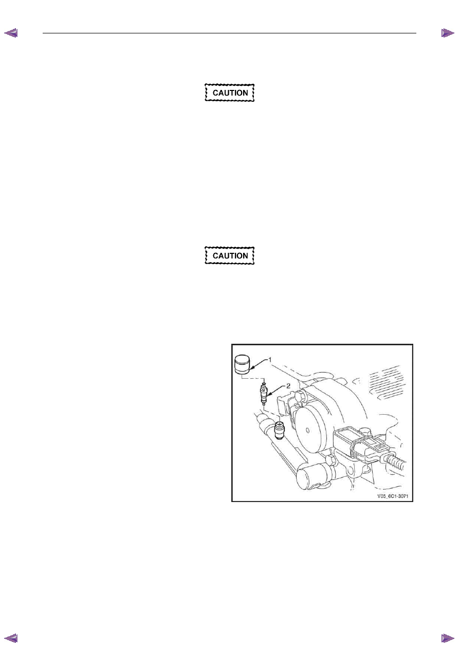
2.21 Schrader Valve – Fuel Pressure Gauge
Connection Point
If the Schrader valve is to be removed but not
replaced immediately, it is advisable to
disconnect the battery to avoid possible fuel
discharge if an accidental attempt is made to
start the engine.
Disconnection of the battery affects vehicle
electronic systems. Refer to 6D1-3 Battery –
V6 before disconnecting the battery.
Remove
1
Depressurise the fuel system, refer to 6C Fuel System - V6.
2
Turn the ignition off.
A small amount of fuel may be released when
servicing the fuel pressure test point. To
reduce the chance of personal injury, cover
the fuel pressure test point with a shop towel
to absorb any fuel spillage when the Schrader
valve sealing cap and Schrader valve are
removed. After the procedure, place the towel
in an approved container for disposal.
3
Remove the Schrader valve sealing cap (1).
4
Remove the Schrader valve (2) using a standard valve
core removal tool.
Figure 6C1-3 – 65
Reinstall
Reinstallation of the Schrader valve is the reverse of the removal procedure, noting the following:
1
Inspect the fuel rail and quick connect fitting for leaks, refer to 6C Fuel System - V6.
2
Road test the vehicle and check for correct operation.
Нет комментариевНе стесняйтесь поделиться с нами вашим ценным мнением.
Текст