Isuzu KB P190. Manual — part 891
Engine Management – V6 – Service Operations
Page 6C1-3–40
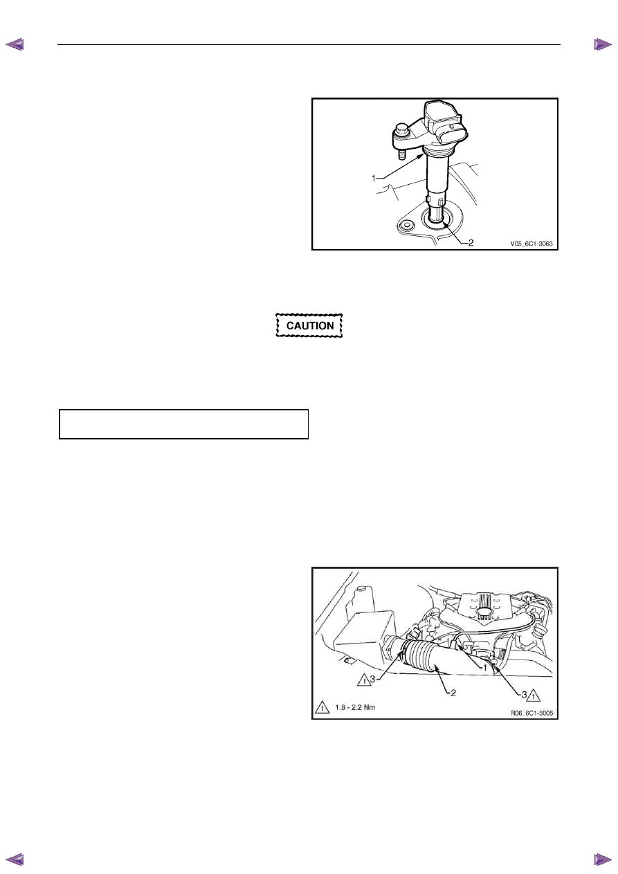
Reinstall
Reinstallation of the ignition coil is the reverse of the removal procedure, noting the following:
1
Lubricate the ignition coil sealing rubber (1) with clean
engine oil, and the inside of the ignition coil boot (2)
with talcum powder.
Figure 6C1-3 – 53
2
Reinstall the ignition coil by pushing down on the ignition coil to engage the sealing rubber in the camshaft cover.
Ensure the ignition coil is fully seated before
tightening the attaching bolt to the specified
torque.
3
Reinstall the ignition coil bolt and tighten to the correct torque specification.
Ignition coil attaching bolt
torque specification . . . . . . . . ...7.0 – 11.0 Nm
4
Road test the vehicle and check for correct operation.
2.16 Intake Air Duct Assembly
Remove
1
Turn the ignition switch off.
2
Disconnect the crankcase ventilation hose (1) from the air intake duct (2).
3
Loosen the two air intake duct retaining clamps (3),
4
Pull the air intake duct away from the throttle body.
5
Pull the air intake duct away from the mass air flow
sensor.
Figure 6C1-3 – 54
Reinstall
Reinstallation of the air intake duct is the reverse of the removal procedure, noting the following:
Engine Management – V6 – Service Operations
Page 6C1-3–41
Ensure the air intake duct sealing rubber is
correctly positioned on the throttle body.
Failure to do this may result in engine
damage due to unfiltered air entering the
engine intake system.
1
Reinstall the air intake duct and tighten the retaining clamps to the correct torque specification.
Air intake duct retaining clamp
torque specification . . . . . . . . . .1.8 – 2.2 Nm
2
Road test the vehicle and check for correct operation, taking particular note that no air leaks are evident.
2.17 Intake Air Temperature Sensor
The intake air temperature (IAT) sensor is part of the mass air flow (MAF) sensor assembly, refer to 2.20
Mass Air
Flow Sensor for the replacement procedure.
Test
To prevent component damage use connector
test adaptor kit J 35616-A.
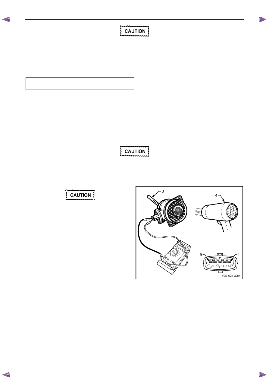
Resistance Check
Do not use a high temperature heat gun as
damage to the MAF sensor will result.
1
Connect a digital ohmmeter using connector test
adaptor kit J 35616-A to the MAF sensor.
2
Whilst holding a thermometer (3), use a commercially
available hair dryer (4) to blow warm air through the
MAF sensor.
3
Measure the resistance across terminals 1 and 2.
Figure 6C1-3 – 55
Engine Management – V6 – Service Operations
Page 6C1-3–42
4
Observe the resistance values as the temperature
increases and compare the temperature / resistance
change to the specifications.
5
If the resistance is not within specifications, replace
the MAF sensor.
Intake Air Temperature Vs Resistance
Temperature °C
Resistance – Ohms (
Ω)
-40
35140 – 43760
-20
12660 – 15120
-10
7943 – 9307
0
5119 – 5892
20
2290 – 2551
25
1900 – 2100
40
1096 – 1238
60
565 – 654
80
312 – 370
100
184 – 222
120
114 – 141
140
74 – 93
2.18 Knock Sensor, Bank 2 (LHS)
Remove
1
Turn the ignition switch off.
2
Disconnect Bank 2 pre-catalytic converter HO2S wiring harness connector, refer to 2.14
Heated Oxygen
Sensor.
3
Raise the front of the vehicle and support on safety stands. Refer to 0A General Information for location of the
jacking points.
4
Remove the starter motor heat shield, refer to 6D1-2 Starting System – V6.
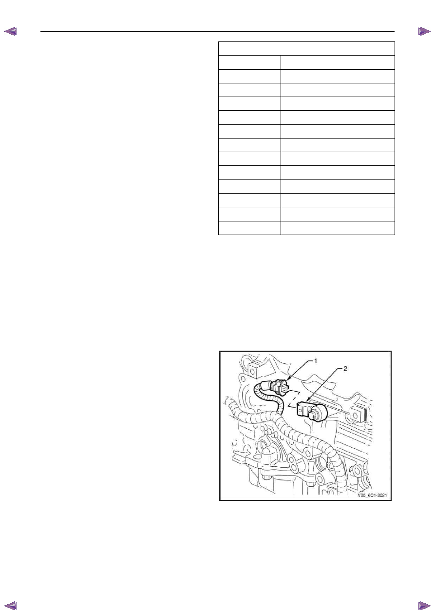
5
Disconnect the wiring harness connector (1) from the
knock sensor (2).
Figure 6C1-3 – 56

Engine Management – V6 – Service Operations
Page 6C1-3–43
6
Remove the bolt (1) attaching the knock sensor (2) to
the engine block and remove the knock sensor.
Figure 6C1-3 – 57
Reinstall
Reinstallation of the knock sensor is the reverse of the removal procedure, noting the following:
1
Ensure the knock sensor mounting surface is flat and free of any dirt, oxidisation, etc.
Ensure the knock sensor is fully seated and
correctly aligned before tightening the
attaching bolt.
Do not over-tighten the attaching bolt as
incorrect operation of the knock sensor may
result.
2
Reinstall the knock sensor and bolt (1). Align the
knock sensor so that it is parallel to the engine oil pan
mounting surface (2), ± 3° (3).
3
Tighten the knock sensor bolt to the correct torque
specification.
Knock sensor attaching bolt
torque specification . . . . . . . . .21.0 – 25.0 Nm
4
Road test the vehicle and check for correct operation,
taking particular note that no exhaust leaks are
evident.
Figure 6C1-3 – 58
2.19 Knock Sensor, Bank 1 (RHS)
Remove
1
Turn the ignition switch off.
2
Raise the front of the vehicle and support on safety stands, refer to 0A General Information for location of the
jacking points.
Нет комментариевНе стесняйтесь поделиться с нами вашим ценным мнением.
Текст