Isuzu KB P190. Manual — part 819
Engine Management – V6 – General Information
Page 6C1-1–34
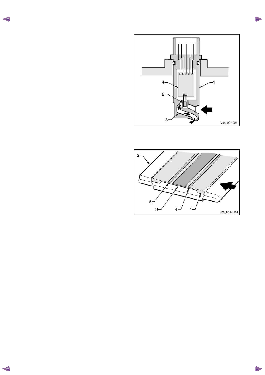
Construction
Projecting into the MAF sensor body is the compact design
sensor assembly (1), which consists of:
•
the sensor element (2),
•
partial airflow measuring tube (3), and
•
integrated evaluation electronics (4).
Figure 6C1-1 – 45
Operation
A diaphragm (1) on the sensor element (2) is heated by a
centrally mounted heater resistor (3), which is held at a
constant temperature. The temperature drops sharply each
side of the heating zone.
Temperature of the diaphragm is registered to the
evaluation electronics by two temperature-dependent
resistors located on the upstream (4) and downstream (5)
side of the resistor.
With no air flow through the air flow measuring tube and
over the sensor element, the temperature characteristic is
the same each side of the heating zone and the resistance
values are identical.
As air flows over the sensor element, the upstream resistor
value alters due to the cooling effect of the air flow. As the
air flows over the heating zone the air temperature is
increased.
Figure 6C1-1 – 46
The air then passes over the downstream resistor and alters the resistance value, but as the air temperature is higher,
the value is different to the upstream resistor. This change in temperature creates a temperature differential between the
two resistors.
It is this differential that is used to calculate the air mass flow, which is independent of absolute temperature. The
differential is also directional, which means the MAF not only measures the mass of the incoming air, but also its
direction.
As the evaluation electronics are measuring the resistance differential between the resistors, the air mass flow for the
entire amount of air passing through the MAF is calculated and sent to the ECM as an analogue signal of 0 – 5 V.
The ECM can also detect air flow that is inappropriate for a given operating condition based on the signal voltage, or a
signal that appears to be fixed based on the lack of normal signal fluctuations expected during engine operation.
Tech 2 can display the MAF value in grams per second (g/s). Values should change rather quickly on acceleration, but
should remain fairly stable at any given engine speed.

Engine Management – V6 – General Information
Page 6C1-1–35
5
Abbreviations and Glossary of
Terms
Abbreviations and terms used in this Section are listed below in alphabetical order with an explanation of the
abbreviation or term.
Abbreviation Description
A/C Air-conditioning
AC
Alternating Current – An electrical current where the polarity is constantly changing between positive and
negative
A/F
Air / Fuel (A/F Ratio)
Analogue Signal
An electrical signal that constantly varies in voltage within a given parameter
Barometric Pressure
Barometric absolute pressure (atmospheric pressure)
CAN
Controller Area Network – A type of serial data for communication between electronic devices.
Catalytic Converter
A muffler-shaped device fitted in the exhaust system, usually close to the engine. Through chemical reaction,
a catalytic converter converts harmful gases produced by the combustion process such as HC, CO, and NOx,
into environmentally safe water vapour, carbon dioxide, and nitrogen.
CKT Circuit
Closed Loop
A fuel control mode of operation that uses the signal from the exhaust oxygen sensor(s), to control the air / fuel
ratio precisely at a 14.7 to 1 ratio. This allows maximum efficiency of the catalytic converter.
CO
Carbon Monoxide. One of the gases produced by the engine combustion process.
DC Direct
Current
Digital Signal
An electrical signal that is either on or off.
DLC
Data Link Connector. Used at the assembly plant to evaluate the engine management system. For service, it
allows the use of Tech 2 in performing system checks.
DLC Data Stream
An output from the ECM initiated by Tech 2 and transmitted via the Data Link Connector(DLC).
DMM (10 M
Ω)
Digital Multimeter. A multipurpose meter that has capability of measuring voltage, current flow and resistance.
A digital multimeter has an input impedance of 10 M
Ω (megohms), which means they draw very little power
from the device under test, they are very accurate and will not damage delicate electronic components
Driver
An electronic device, usually a power transistor, that operates as an electrical switch.
DTC
Diagnostic Trouble Code. If a fault occurs in the engine management system, the ECM may set a four digit
diagnostic trouble code (DTC) which represents the fault condition. Tech 2 is used to interface with the ECM
and access the DTC(s). The ECM may also operate the malfunction indicator lamp in the instrument cluster.
Duty Cycle
The time, in percentage, that a circuit is on versus off.
ECT Sensor
Engine Coolant Temperature sensor. A device that provides a variable voltage to the ECM based on the
temperature of the engine coolant.
EEPROM
Electrically Erasable Programmable Read Only Memory. A type of read only memory (ROM) that can be
electrically programmed, erased and reprogrammed using Tech 2. Also referred to as Flash Memory
EMI or Electrical
Noise
An unwanted signal interfering with a required signal. A common example is the effect of high voltage power
lines on an AM radio.
Engine Braking
A condition where the engine is used to slow the vehicle on closed throttle or low gear.
EPROM
Erasable Programmable Read Only Memory. A type of Read Only Memory (ROM) that can be erased with
ultraviolet light and then reprogrammed.
ESD
Electrostatic Discharge. The discharge of static electricity which has built up on an insulated material
EVAP
Evaporative emission control system. Used to prevent fuel vapours from the fuel tank from entering into the
atmosphere. The vapours are stored in a canister that contains an activated charcoal element. The fuel
vapours are purged from the canister into the manifold to be burned in the engine.
GM LAN
General Motors Local Area Network - A type of serial data for communication between electronic devices.
Fuse
A thin metal strip which melts when excessive current flows through it, creating an open circuit and protecting
a circuit from damage.
HC
Hydrocarbon. Result of unburned fuel produced by incomplete combustion.
Heavy Throttle
Approximately 3/4 of accelerator pedal travel (75% throttle position)
IAT Sensor
Intake Air Temperature sensor. A device that provides a variable voltage to the ECM based on the
temperature of air entering the intake system.
Ideal Mixture
The air / fuel ratio which provides the best performance, while maintaining maximum conversion of exhaust
emissions, typically 14.7 to 1 on spark ignition engines
IGN Ignition
Inputs
Information from sensors (MAF, TP, etc.) and switches (A/C request, etc.) used by the ECM to determine how
to control its outputs.

Engine Management – V6 – General Information
Page 6C1-1–36
Intermittent
An electrical signal that occurs now and then; not continuously. In electrical circuits, refers to occasional open,
short, or ground in a circuit
Light Throttle
Approximately 1/4 of accelerator pedal travel (25% throttle position)
Low
A voltage less than a specific threshold. Operates the same as a ground and may, or may not, be connected
to chassis ground.
MAF Sensor
Mass Air Flow Sensor. A device that provides a variable voltage to the ECM based on the amount of air flow
entering in the intake system.
Medium Throttle
Approximately 1/2 of accelerator pedal travel (50% throttle position)
N.C
Normally Closed. Switch contacts that are closed when they are in the normal operating position
N.O
Normally Open. Switch contacts that are normally open when in the normal operating position
NOx
Nitrogen Oxide. One of the pollutants found in spark ignition engine exhaust that is formed from normal
combustion and increases in severity with combustion temperature.
O2 Sensor
Oxygen Sensor. A device located in the exhaust system that provides a variable voltage to the ECM based on
the oxygen content of exhaust gas.
May also include a heating circuit to provide faster initial warm-up (HO2 sensor).
OBD
On Board Diagnostic
Open Loop
ECM control of the fuel control system without the use of the oxygen sensor signal.
Output
Functions that are controlled by the ECM, typically these can include solenoids and relays, etc.
ECM
Engine Control Module. An electronic device which controls the engine management system.
ECU
Electronic Control Unit. An electronic device which controls specific system functions
PCV
Positive Crankcase Ventilation. Method of reburning crankcase fumes rather than passing them directly into
the atmosphere
PIM
Powertrain Interface Module – The PIM acts as a communication translator between the ECM and other on-
board controllers that use a different serial data protocol.
PM Permanent
Magnet
PWM
Pulse Width Modulated. A digital signal turned on and off for a percentage of available cycle time. A signal that
is 30% on and 70% of would be termed a 30% on PWM signal.
Quad Driver
A transistor in the ECM capable of operating four separate outputs. Outputs can be either on-off or pulse width
modulated.
RAM
Random Access Memory. A microprocessor can write into or read from this memory as needed. This memory
is volatile and needs a constant power supply to be retained. If the power is lost or removed, RAM data is lost.
r.p.m.
Revolutions Per Minute
Serial Data
Serial data is a series of rapidly changing voltage signals pulsed from high to low. These signals are typically
transmitted through a wire often referred to as the Serial Data Circuit.
SFI
Sequential Fuel Injection. Method of injecting fuel into the engine one cylinder at a time in relation to the
engines firing order.
Solenoid
An electromagnetic coil which creates a magnetic field when current is applied, causing a plunger or ball to
move.
Switch
Device to opens and close a circuit, thereby controlling current flow.
Tech 2
Tech 2 is a peripheral device that aids in the diagnosis and repair of electronic systems such as engine
management, transmission control etc. Tech 2 connects to the vehicle’s Data Link Connector (DLC).
TP Sensor
Throttle Position sensor. A device that provides a variable voltage to the ECM based on the position of the
throttle plate.
Vacuum – manifold
Vacuum sourced downstream of the throttle plate.
Vacuum – ported
Vacuum sourced upstream of the throttle plate.
VSS
Vehicle Speed Sensor. A permanent magnet type device that provides a digital voltage to the ECM.
WOT
Wide Open Throttle – Full travel of the accelerator pedal (100% throttle position).

Engine Management – V6 – Diagnostics
Page 6C1-2–1
6C1-2 Engine Management – V6
Diagnostics
A T T E N T I O N
Before performing any service operation or other procedure described in this Section, refer to 1.5 Warning
Caution and Notes for correct workshop practices with regard to safety and/or property damage.
1
General Information . . . . . . . . . . . . . . . . . . . . . . . . . . . . . . . ...4
1.1
Diagnostic System Check . . . . . . . . . . . . . . . . . . . . . . . . . . . . . . . . . . 4
1.2
Diagnostic Trouble Code Tables . . . . . . . . . . . . . . . . . . . . . . . . . . . . . . .. 4
1.3
Symptoms Diagnostics . . . . . . . . . . . . . . . . . . . . . . . . . . . . . . . . . . . 5
1.4
Diagnostic Trouble Codes . . . . . . . . . . . . . . . . . . . . . . . . . . . . . . . . . 5
1.5
Warning Caution and Notes. . . . . . . . . . . . . . . . . . . . . . . . . . . . . . . . .. 6
2
GM LAN Serial Communication Circuit . . . . . . . . . . . . . . . . . . . . . . . . 8
3
Wiring Diagrams and Connector Charts . . . . . . . . . . . . . . . . . . . . . . . ..9
3.1
Wiring Diagrams . . . . . . . . . . . . . . . . . . . . . . . . . . . . . . . . . . . . . 9
3.2
ECM Connector End Views . . . . . . . . . . . . . . . . . . . . . . . . . . . . . . . . . 12
3.2
Engine Control Connector End Views . . . . . . . . . . . . . . . . . . . . . . . . . . . ... 16
4
Diagnostics Starting Point. . . . . . . . . . . . . . . . . . . . . . . . . . . . ...18
4.1
Basic Requirements . . . . . . . . . . . . . . . . . . . . . . . . . . . . . . . . . . . 18
4.2
Diagnostic Precautions . . . . . . . . . . . . . . . . . . . . . . . . . . . . . . . . . ... 18
4.3
Preliminary Checks. . . . . . . . . . . . . . . . . . . . . . . . . . . . . . . . . . . .. 19
4.4
Diagnostic System Check . . . . . . . . . . . . . . . . . . . . . . . . . . . . . . . . ... 20
5
Symptoms Diagnostics. . . . . . . . . . . . . . . . . . . . . . . . . . . . . . 22
5.1
Symptoms Diagnosis Table . . . . . . . . . . . . . . . . . . . . . . . . . . . . . . . . 22
5.2
Intermittent Fault Conditions. . . . . . . . . . . . . . . . . . . . . . . . . . . . . . . .. 22
5.3
Backfire. . . . . . . . . . . . . . . . . . . . . . . . . . . . . . . . . . . . . . . . . 24
5.4
Cranks But Does Not Run . . . . . . . . . . . . . . . . . . . . . . . . . . . . . . . . ... 26
5.5
Cuts Out, Misses. . . . . . . . . . . . . . . . . . . . . . . . . . . . . . . . . . . . .. 27
5.6
Detonation / Spark Knock . . . . . . . . . . . . . . . . . . . . . . . . . . . . . . . . ... 28
5.7
Dieseling, Run-on . . . . . . . . . . . . . . . . . . . . . . . . . . . . . . . . . . . . 28
5.8
Hard Start . . . . . . . . . . . . . . . . . . . . . . . . . . . . . . . . . . . . . . . . 29
5.9
Hesitation, Sag and Stumble . . . . . . . . . . . . . . . . . . . . . . . . . . . . . . . .. 30
5.10
Lack of Power, Sluggishness or Sponginess . . . . . . . . . . . . . . . . . . . . . . . . ... 31
5.11
Poor Fuel Economy . . . . . . . . . . . . . . . . . . . . . . . . . . . . . . . . . . . . 32
5.12
Rough, Unstable, Incorrect Idle or Stalling . . . . . . . . . . . . . . . . . . . . . . . . . ... 34
5.13
Surges / Chuggles . . . . . . . . . . . . . . . . . . . . . . . . . . . . . . . . . . . ... 35
6
Functional Checks. . . . . . . . . . . . . . . . . . . . . . . . . . . . . . . . 37
6.1
General Information. . . . . . . . . . . . . . . . . . . . . . . . . . . . . . . . . . . . 37
6.2
Fuel Injector Coil Test . . . . . . . . . . . . . . . . . . . . . . . . . . . . . . . . . . . 37
6.3
Fuel Injector Balance Test . . . . . . . . . . . . . . . . . . . . . . . . . . . . . . . . .. 42
6.4
Fuel Injector Leak Down Test . . . . . . . . . . . . . . . . . . . . . . . . . . . . . . . . 44
6.5
Alcohol / Contaminants in Fuel Diagnosis . . . . . . . . . . . . . . . . . . . . . . . . . . 46
6.6
Crankshaft Position (CKP) System Variation Learn Procedure. . . . . . . . . . . . . . . . . ... 46
6.7
Throttle Body Relearn. . . . . . . . . . . . . . . . . . . . . . . . . . . . . . . . . . .. 47
Нет комментариевНе стесняйтесь поделиться с нами вашим ценным мнением.
Текст