Isuzu KB P190. Manual — part 818
Engine Management – V6 – General Information
Page 6C1-1–30
Similar to the two-step HO2S, measurement is achieved by
comparing the oxygen content of the exhaust gas to the
oxygen content of a reference gas. However, the way in
which the ECM calculates the exhaust oxygen content is
different, and results in a continual signal. This allows the
ECM to monitor not only whether the fuel mixture is rich or
lean, but exactly how rich or how lean. The wide-band
HO2S is basically a two-step HO2S with the addition of a
pump cell.
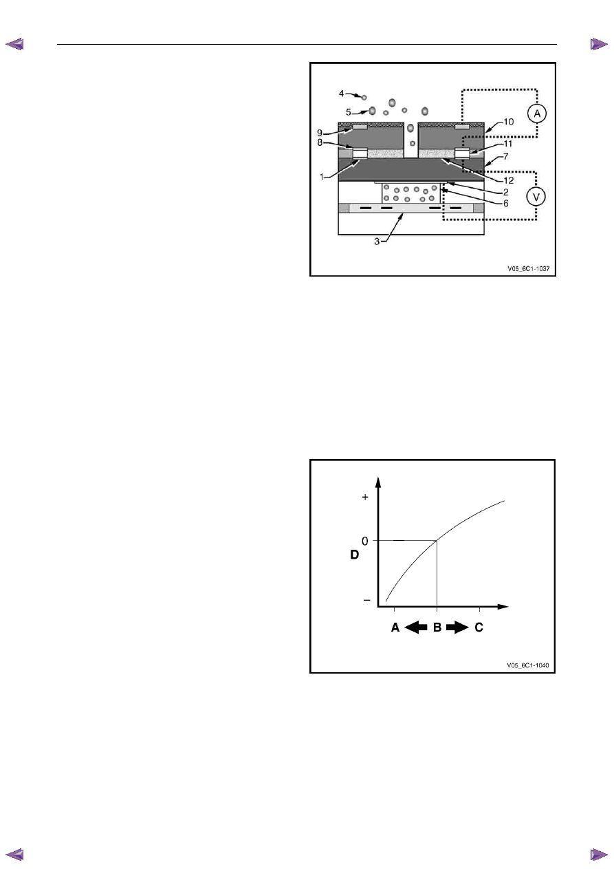
The ECM applies a pump voltage across the pump cell,
which causes oxygen to be pumped from the exhaust gas
into or out of the diffusion gap through the diffusion barrier.
While monitoring the Nernst cell, the ECM varies the pump
current so the gas in the diffusion gap remains constant at
an A/F ratio of 14.7:1 (Nernst cell output of 450 mV).
Legend
1 Outer
Electrode
2 Inner
Electrode
3 Heater
Element
4
Oxygen Molecule (in exhaust stream)
5
Other Molecules (in exhaust stream)
6
Reference Gas (outside air)
7 Nernst
Cell
8
Pump Cell Electrode
9
Pump Cell Electrode
10
Pump Cell
11 Diffusion
Gap
12
Porous Diffusion Barrier
A Pump
Current
V
Nernst Cell Voltage
Figure 6C1-1 – 36
If the exhaust gas is lean, the pump cell pumps oxygen to
the outside (positive pump current). If the exhaust gas is
rich, oxygen is pumped from the exhaust gas into the
diffusion gap (negative pump current). By monitoring how
much it has to vary the pumping current, the ECM
determines the exact A/F ratio.
Legend
A Rich
Mixture
B
A/F Ratio 14.7:1 (Lambda = 1)
C Lean
Mixture
D Sensor
Current
Figure 6C1-1 – 37
Engine Management – V6 – General Information
Page 6C1-1–31
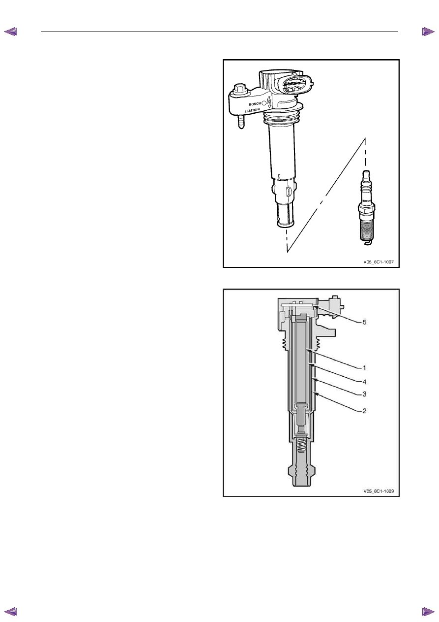
4.15 Ignition Coil and Spark Plug
Long-life platinum tip spark plugs are used which, along with
the ignition coil spark plug boot and spring, require
replacement at 100,000 kilometre service intervals. The
spark plugs, featuring a J-gap and a conical seat, do not
require inspection between services, and must not be re-
gapped.
Individual pencil-type ignition coils, one for each cylinder, are
mounted in the centre of the camshaft covers, and have
short boots connecting the coils directly to the spark plugs.
The pencil coil makes use of the space available in the spark
plug cavity in the cylinder head and camshaft cover. As a
pencil coil is always mounted directly on to the spark plug,
no high-tension ignition leads are required, further enhancing
reliability.
Figure 6C1-1 – 38
Pencil coils operate similarly to other compact coils, however
due to their shape, the structure differs considerably.
The central rod core (1) consists of laminations of varying
widths, stacked in packs that are nearly spherical. A yoke
plate (2), made from layered electrical sheet steel, provides
the magnetic circuit. The primary winding (3) is located
around the secondary winding (4), which supports the core.
A printed circuit board, or driver module, (5) is located at the
top of the coil and controls the firing of the coil based on
input from the ECM.
The ECM is responsible for maintaining correct spark timing
and dwell for all driving conditions. The ECM calculates the
optimum spark parameters from information received from
the various sensors, and triggers the appropriate ignition
module which then operates the coil.
The ignition coil / modules are supplied with the following
circuits:
•
Ignition feed circuit.
•
Ground circuit.
•
Ignition control circuit.
•
Reference low circuit.
Figure 6C1-1 – 39
Engine Management – V6 – General Information
Page 6C1-1–32
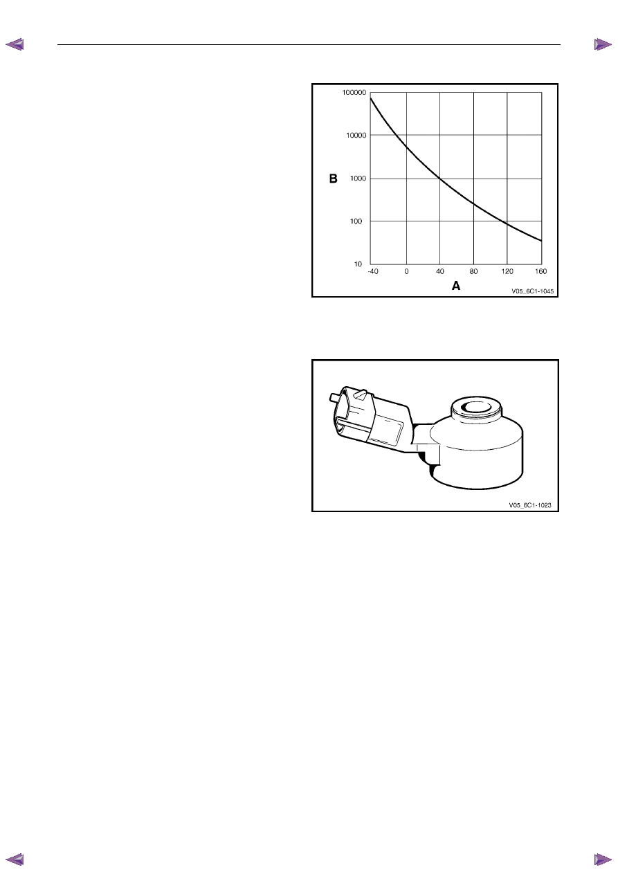
4.16 Intake Air Temperature Sensor
The intake air temperature (IAT) sensor is a thermistor,
which is a resistor that changes it’s resistance value based
on temperature.
The IAT sensor is part of the air mass sensor and is not a
serviceable item. The sensor is a negative temperature
coefficient (NTC) type, intake air temperature produces a
high sensor resistance while high engine coolant
temperature causes low sensor resistance.
Legend
A Temperature
B Resistance
The ECM provides a 5 V reference signal to the IAT and
monitors the return signal which enables it to calculate the
intake air temperature.
The ECM uses this signal to make corrections to the
operating parameters of the system based on changes in air
intake temperature.
Figure 6C1-1 – 40
4.17 Knock
Sensor
The knock sensor (KS) signal is used by the ECM to provide
optimum ignition timing while minimising engine knock or
detonation.
The ECM monitors the voltage of the left-hand (Bank 2)
sensor during the 45 degrees after cylinder 2, 4, or 6 has
fired and the voltage of the right-hand (Bank 1) sensor
during the 45 degrees after cylinder 1, 3, or 5 has fired.
If knock occurs in any of the cylinders, the ignition will be
retarded by three degrees for that particular cylinder. If the
knocking then stops, the ignition will be restored to what it
was before in steps of 0.75 degrees.
Should knocking continue in the same cylinder despite of
the ignition being retarded, the ECM will retard the ignition
an additional step of three degrees, and so on, up to a
maximum of 12.75 degrees. The ignition will also be
retarded at high ambient temperatures to counteract
knocking tendencies provoked by high intake air
temperatures.
Should either Bank 1 or Bank 2 sensor fail to work, or
should an open circuit occur, the ignition timing will then be
set at a default strategy that will retard the ignition much
more than normal.
Figure 6C1-1 – 41
Engine Management – V6 – General Information
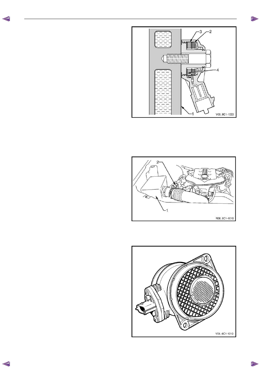
Page 6C1-1–33
The knock sensor is tuned to detect the frequency of the
vibration created by combustion knock. The vibration is
transferred to the knock sensor through the cylinder
block (1).
Inside the sensor is a mass (2) that is excited by this
vibration, and the mass exerts a compressive force onto a
piezo-ceramic element (3). The compressive force causes a
charge transfer inside the element, so that an AC voltage
appears across the two outer faces (4) of the element. The
amount of the AC voltage produced is proportional to the
amount of knock.
Figure 6C1-1 – 42
4.18 Mass Air Flow Sensor
Air Intake System
The air intake system draws outside air through an air
cleaner assembly (1). The air is then routed through a mass
air flow (MAF) sensor (2) and into the throttle body and
intake manifold. The air is then directed into the intake
manifold runners, through the cylinder heads and into the
cylinders.
An arrow marked on the body of the MAF sensor indicates
correct air flow direction. The arrow must point toward the
engine.
Figure 6C1-1 – 43
Mass Air Flow Sensor
A hot film type mass air flow (MAF) sensor is used which
measures the air mass inducted into the engine, regardless
of the engine’s operating state. The MAF precisely
measures a portion of the total airflow and takes into
account the pulsation and reverse flows generated by the
engine’s inlet and exhaust valves.
Changes in intake air temperature have no effect on
measuring accuracy.
Figure 6C1-1 – 44
Нет комментариевНе стесняйтесь поделиться с нами вашим ценным мнением.
Текст