Isuzu KB P190. Manual — part 258
ENGINE ELECTRICAL 6D – 31
24. Through Bolt
Install the through bolts in the rear cover and tighten them
to the specified torque.
Through Bolt Torque
N
⋅m (kg⋅m/lb⋅ft)
8.1 (0.83/6.00)
065RY00044
RTW46DSH002601
25. Lead Wire
Connect the lead wire in the magnetic switch and tighten
the terminal nut to the specified torque.
Lead Wire Terminal Nut Torque
N
⋅m (kg⋅m/lb⋅ft)
8.6 (0.88/6.40)
RTW46DSH005801
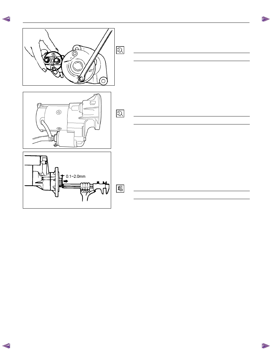
Inspection After Assembly
Use a vernier caliper to measure the pinion shaft thrust
play.
The pinion shaft thrust play is equal to the pinion shaft end
and pinion stopper clearance.
Pinion Shaft Thrust Play
mm (in)
0.1 – 2.0 (0.004 – 0.078)
6D – 32 ENGINE ELECTRICAL
MAGNETIC SWITCH
The following tests must be performed with the starter
motor fully assembled.
The yoke lead wire must be disconnected from the “M”
terminal.
To prevent coil burning, complete each test as quickly as
possible (within three to five seconds).
RTW46DSH004601
Temporarily connect the solenoid switch between the
clutch and the housing and run the following test.
Complete each test within three to five seconds.
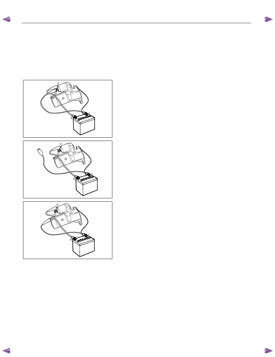
1. Pull-in
Test
Connect the battery negative terminal with the solenoid
switch body and the M terminal. When current is applied to
the S terminal from the battery positive terminal, the pinion
should flutter.
RTW46DSH005901
2. Hold-in Maintenance Test
Disconnect the lead at the M terminal. The pinion should
continue to flutter.
RTW46DSH004701
3. Return
Test
Disconnect the battery positive lead at the S terminal.
The pinion should return to its home position.
ENGINE ELECTRICAL 6D – 33
PRE-HEATING SYSTEM
INSPECTION AND REPAIR
Make the necessary adjustments, repairs, and part replacement if excessive wear of damage is discovered during
inspection.
VISUAL CHECK
Check the main fuses and glow indicator for damage.
Replace the part(s) if required.
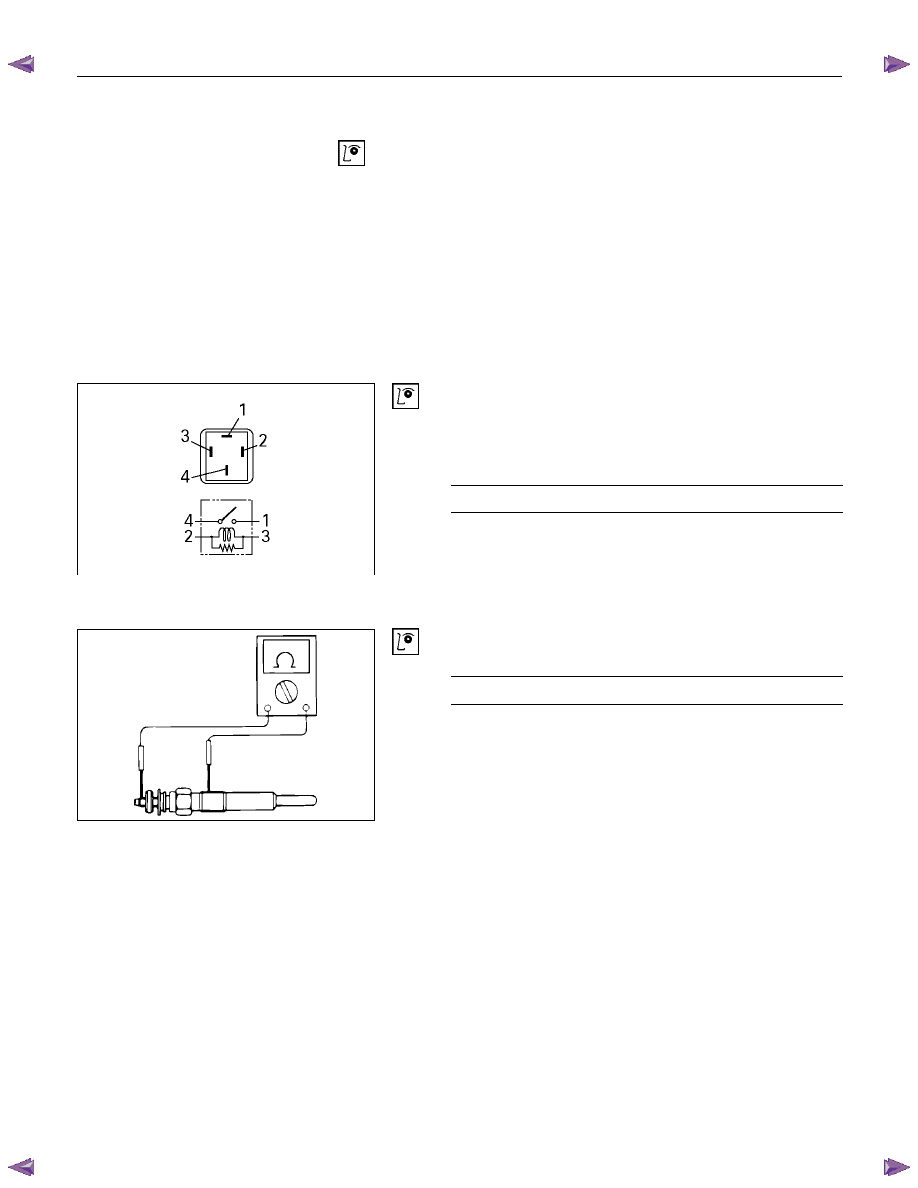
GLOW RELAY
The glow relay is located in the relay box the engine
compartment.
825R300046
Use an ohmmeter to measure the resistance between
terminals No.2 and No.3.
If the measured value is outside the specified range, the
glow relay must be replaced.
Glow Relay Resistance
Ohms
94
− 114
GLOW PLUG
LNW21KSH001401
Use a circuit tester to test the glow plugs for continuity.
Glow Plug Resistance (Reference)
Ohms
Approximately 0.9
EGR SYSTEM 4JA1T (L)
Refer to 6F-9. (EGR system diagram)
Engine Control System (4JH1) 6E-1
SECTION 6E
ENGINE CONTROL SYSTEM (4JH1)
TABLE OF CONTENTS
Specifications . . . . . . . . . . . . . . 6E-4
Schematic And Routing Diagrams . . . . . . 6E-5
Vacuum Hose Routing Diagram. . . . . .. 6E-5
Engine Controls Schematics . . . . . . ... 6E-7
Component Locator. . . . . . . . . . . 6E-18
Engine Controls Component Views . . . . 6E-18
Engine Control Module (ECM) Connector
End Views . . . . . . . . . . . . . .. 6E-22
Engine Control Connector End Views . . . . 6E-25
Diagnostic Information And Prosedures. . . . 6E-30
Engine Control System Check Sheet . . . .. 6E-30
Diagnostic Starting Point - Engine Controls . 6E-31
Breaker Box . . . . . . . . . . . . . 6E-32
Diagnostic System Check - Engine Controls .. 6E-33
Scan Tool Data List . . . . . . . . . . . 6E-36
Scan Tool Data Definitions. . . . . . . .. 6E-37
Scan Tool Output Controls. . . . . . . .. 6E-40
Scan Tool Does Not Power Up . . . . . ... 6E-41
Scan Tool Does Not Communicate with Keyword
2000 Device . . . . . . . . . . . . ... 6E-42
Lost Communication with The Engine Control
Module (ECM) . . . . . . . . . . . ... 6E-44
Engine Cranks but Does Not Run . . . . ... 6E-47
Diagnostic Trouble Code (DTC) List . . . ... 6E-50
(Flash Code 65) . . . . . . . . . . . . 6E-66
(Flash Code 65) . . . . . . . . . . . 6E-68
(Flash Code 65) . . . . . . . . . . . 6E-70
(Flash Code 65) . . . . . . . . . . . 6E-73
(Flash Code 34) . . . . . . . . . . . 6E-75
(Flash Code 34) . . . . . . . . . . . 6E-78
(Flash Code 34) . . . . . . . . . . . 6E-81
(Flash Code 34) . . . . . . . . . . . 6E-83
(Flash Code 23) . . . . . . . . . . . 6E-85
(Flash Code 23) . . . . . . . . . . . 6E-88
(Flash Code 14) . . . . . . . . . . . 6E-90
(Flash Code 14) . . . . . . . . . . . 6E-93
(Flash Code 15) . . . . . . . . . . . 6E-95
(Flash Code 52. . . . . . . . . . . ... 6E-96
(Flash Code 52) . . . . . . . . . . . 6E-98
(Flash Code 52) . . . . . . . . . . . 6E-100
(Flash Code 52) . . . . . . . . . . . 6E-102
(Flash Code 54) . . . . . . . . . . . 6E-103
(Flash Code 64) . . . . . . . . . . . 6E-107
(Flash Code 64) . . . . . . . . . . . 6E-111
(Flash Code 64) . . . . . . . . . . . .6E-114
(Flash Code 64) . . . . . . . . . . . .6E-118
(Flash Code 65) . . . . . . . . . . . .6E-121
(Flash Code 53) . . . . . . . . . . . 6E-123
(Flash Code 53) . . . . . . . . . . . 6E-125
DTC P0251 (Symptom Code 9, A, B, C)
(Flash Code 53) . . . . . . . . . . . 6E-127
(Flash Code 53) . . . . . . . . . . . 6E-129
(Flash Code 43) . . . . . . . . . . . 6E-130
Нет комментариевНе стесняйтесь поделиться с нами вашим ценным мнением.
Текст