Isuzu KB P190. Manual — part 257
ENGINE ELECTRICAL 6D – 27
RTW46DSH003701
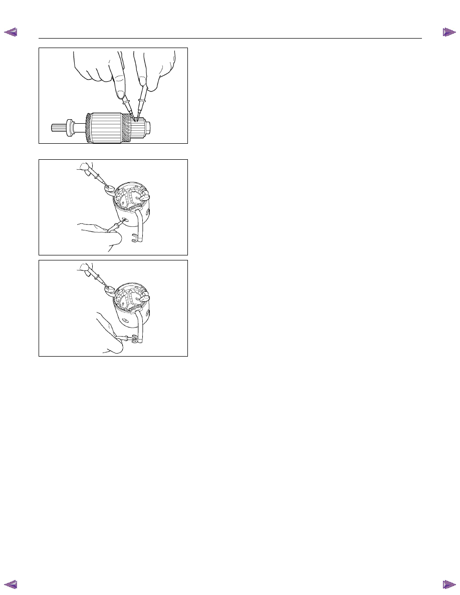
6. Use the circuit tester to check the armature for
continuity.
1
Hold the circuit tester probes against two
commutator segments.
2
Repear Step 1 at different segments of the
armature core.
There should be continuity between all segments of
the commutator.
If there is not, the armature must be replaced.
RTW46DSH003801
YOKE
1. Use a circuit tester to check the field winding ground.
1
Hold one circuit tester probe against the field
winding end or brush.
2
Hold the other circuit tester probe against the bare
surface of the yoke body.
There should be no continuity.
If there is continuity, the field coil is grounded.
The yoke must be replaced.
RTW46DSH003901
2. Use the circuit tester to check the field winding
continuity.
1
Hold one circuit tester probe against the “M”
terminal lead wire.
2
Hold the other circuit tester probe against the field
winding brush.
There should be continuity.
If there is no continuity, the yoke must be replaced.
6D – 28 ENGINE ELECTRICAL
BRUSH AND BRUSH HOLDER
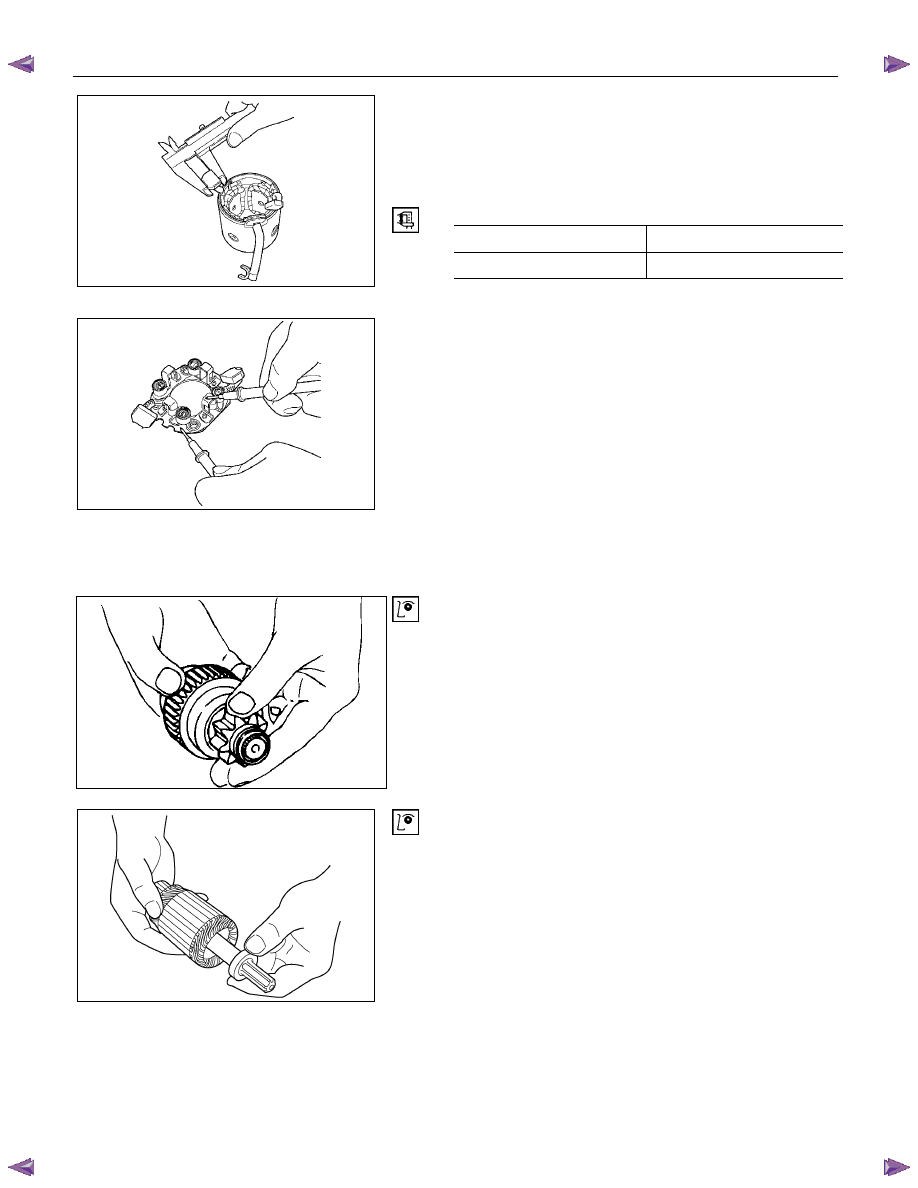
1. Use a vernier caliper to measure the brush length (four
brushes).
Replace the brushes as a set if one or more of the
brush lengths is less than the specified limit.
Brush Length
mm (in)
Standard Limit
15 (0.59)
12 (0.47)
RTW46DSH004001
RTW46DSH004101
2. Use a circuit tester to check the brush holder
insulation.
Touch one probe to the holder plate and the other
probe to the positive brush holder.
There should be no continuity.
3. Inspect the brushes for excessive wear.
If the negative brushes have excessive wear, the
entire brush holder assembly must be replaced.
If the positive brushes have excessive wear, the entire
yoke must be replaced.
OVERRUNNING CLUTCH
1. Inspect the overrunning clutch gear teeth for
excessive wear and damage.
Replace the overrunning clutch if necessary.
2. Rotate the pinion clockwise.
It should turn smoothly.
3. Try to rotate the pinion in the opposite direction.
The pinion should lock.
065RY00035
RTW46DSH004401
BEARING
Inspect the bearings for excessive wear and damage.
Replace the bearings if necessary.
ENGINE ELECTRICAL 6D – 29
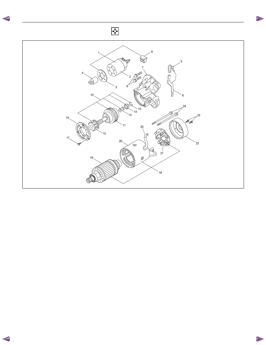
REASSEMBLY
RTW46DLF000601
Reassembly Steps
1. Magnetic switch assembly
14.
Pinion stopper
2. Magnetic switch
15.
Pinion stopper clip
3. Dust cover
16.
Bearing retainer
4. Plunger
17.
Bolt
5. Torsion spring
18.
Motor assembly
6. Shift lever
19.
Armature
7. Gear case
20.
Yoke
8. Dust cover
21.
Brush holder
9. Bolt
22.
Rear
cover
10. Pinion assembly
23.
Screw
11. Clutch
24.
Through
bolt
12. Pinion shaft
25.
Lead wire
13. Rerurn spring
6D – 30 ENGINE ELECTRICAL
RTW46DSH005601
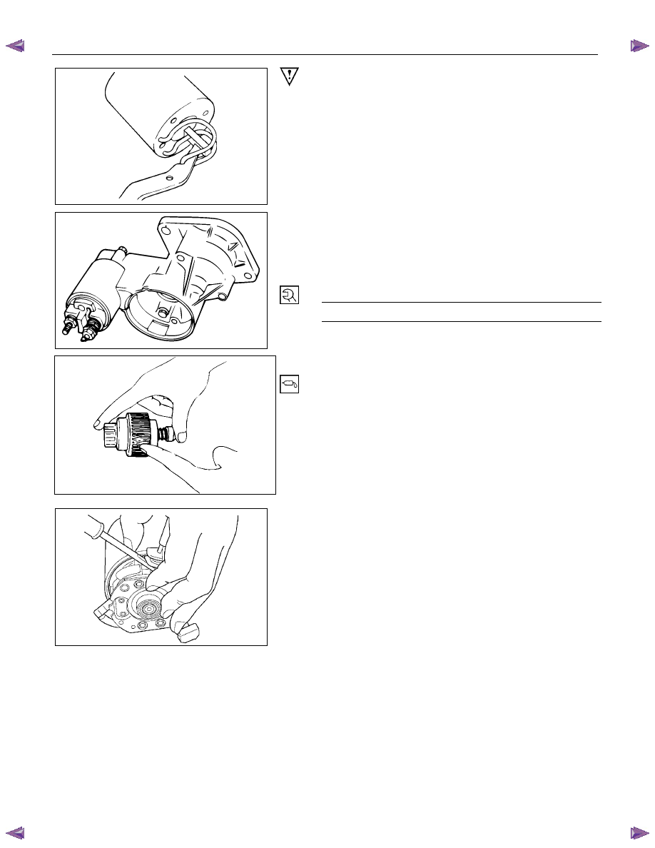
Important Operations
1. Magnetic Switch Assembly
1. Attach the torsion spring to the hole in the magnetic
switch as illustrated.
2. Insert the shift lever into the plunger hole of the
magnetic switch.
RTW46DSH005701
7. Gear
Case
3,8. Dust Cover
1. Install the magnetic switch assembly in the gear case.
2. Install the dust cover.
Dust Cover Bolt Torque
N
⋅m (kg⋅m/lb⋅ft)
8 (0.8/5.4)
10. Pinion Assembly
Apply a coat of grease to the reduction gear and install the
pinion assembly to the armature shaft.
065RY00041
RTW46DSH004501
21. Brush Holders
1. Install the brushes into the brush holder with raising
the spring end of the brush spring.
Take care not to damage the commutator face.
2. Install the brush holder with aligning the peripheries of
the yoke and the brush holder.
Нет комментариевНе стесняйтесь поделиться с нами вашим ценным мнением.
Текст