Isuzu KB P190. Manual — part 256
ENGINE ELECTRICAL 6D – 23
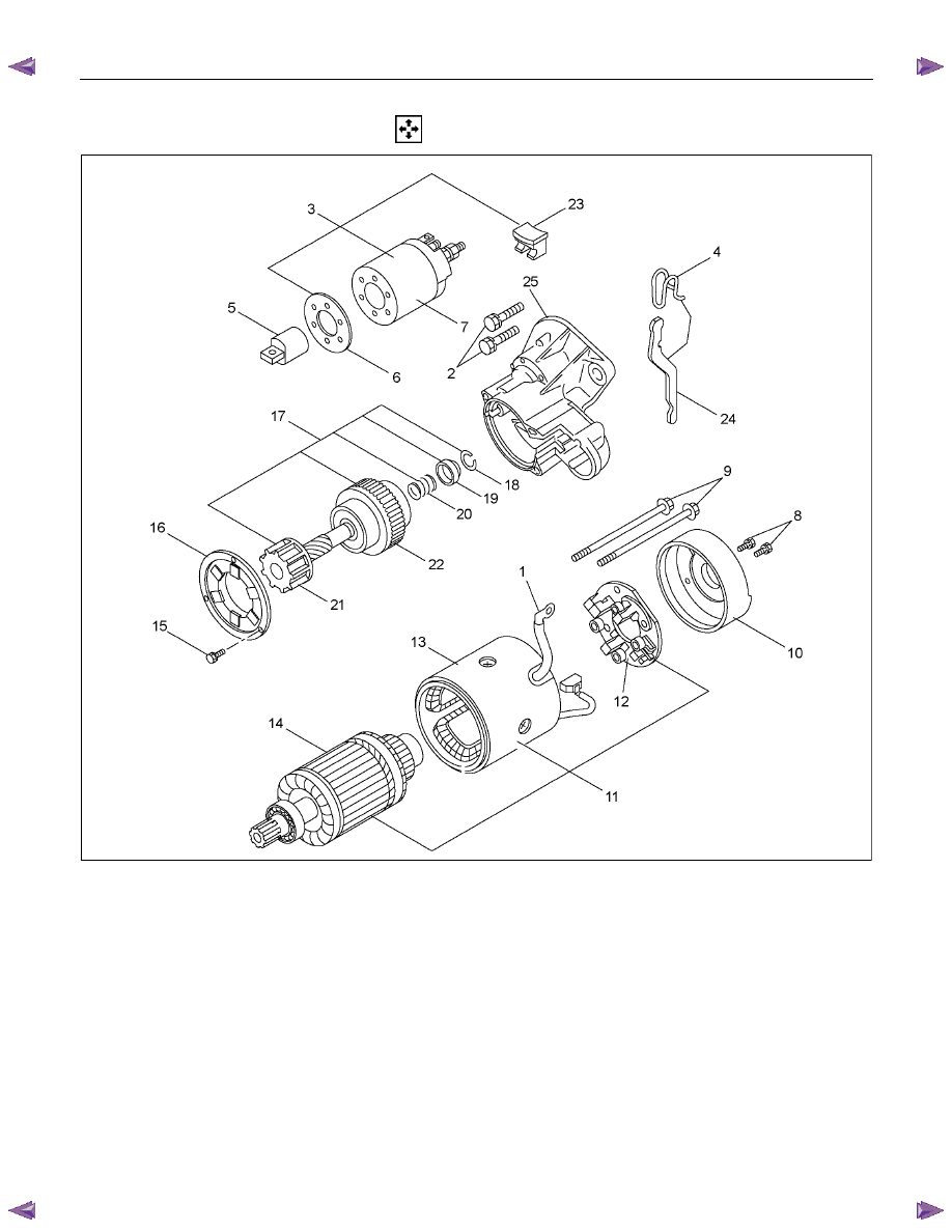
DISASSEMBLY
RTW460LF000201
Disassembly Step
1. Lead wire
14.
Armature
2. Bolt
15.
Bolt
3. Magnetic switch assembly
16.
Bearing retainer
4. Torsion spring
17.
Pinion assembly
5. Plunger
18.
Pinion stopper clip
6. Dust cover
19.
Pinion stopper
7. Magnetic switch
20.
Return spring
8. Screw
21.
Pinion shaft
9. Through bolt
22.
Clutch
10. Rear cover
23.
Dust cover
11. Motor assembly
24.
Shift lever
12. Brush holder
25.
Gear case
13. Yoke
6D – 24 ENGINE ELECTRICAL
RTW46DSH002601
Important Operations
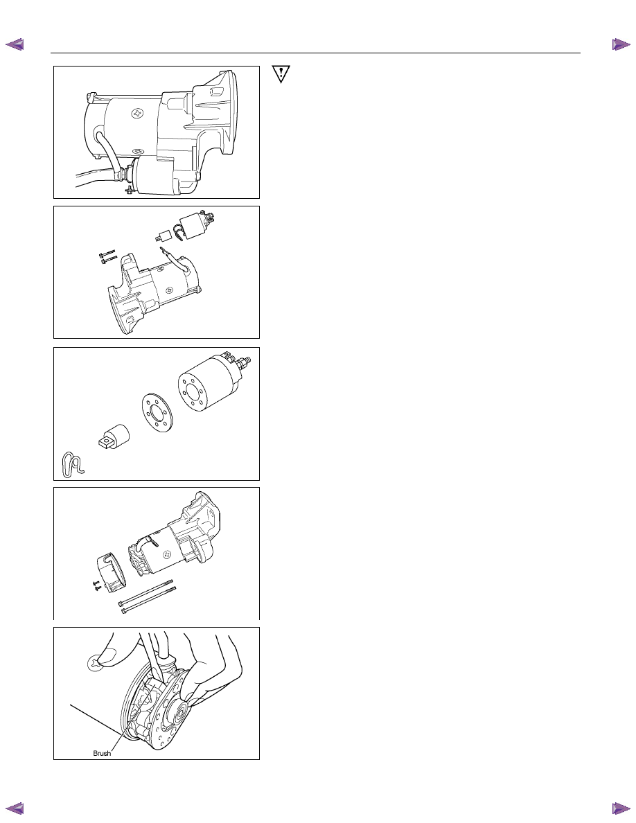
1. Lead
Wire
Disconnect the lead wire at the magnetic switch.
RTW46DSH002701
3. Magnetic Switch Assembly
Remove the magnetic switch bolts, then remove the
switch from the shift lever.
RTW46DSH002801
Remove the torsion spring from the magnetic switch.
RTW46DSH002901
8. Through
Bolt
9. Screw
10. Rear Cover
Remove the through bolts, then remove the rear cover.
RTW46DSH003001
11. Motor Assembly
Remove the four brushes from the brush holders.
ENGINE ELECTRICAL 6D – 25
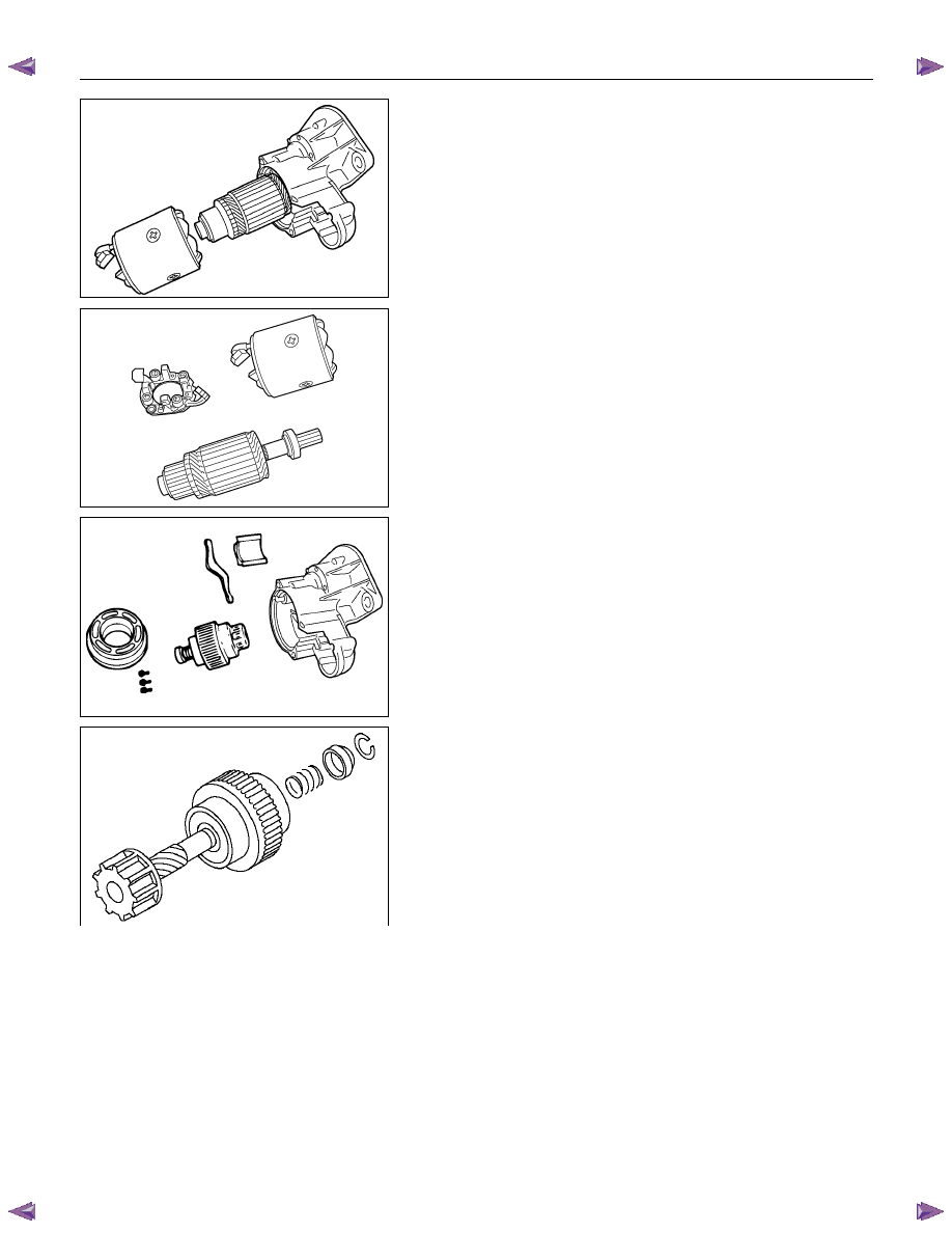
RTW46DSH003101
Remove the yoke along with the armature and the brush
holder from the gear case.
Remove the brushes and commutator carefully so as not
to allow them in contact with the adjacent parts.
RTW46DSH003201
12. Brush Holder
13. Yoke
14. Armature
Remove the brush holder and pull out the armature
assembly free from the yoke.
RTW46DSH003301
16. Bearing Retainer
17. Pinion Assembly
23. Dust Cover
24. Shift Lever
25. Gear Case
1. Remove the bearing retainer.
2. Remove the pinion from the gear case.
RTW46DSH003401
3. Use a screwdriver to remove the stopper clip. Then
disassemble the pinion assembly.
6D – 26 ENGINE ELECTRICAL
INSPECTION AND REPAIR
Make the necessary adjustments, repairs, and part replacement if excessive wear or damage is discovered during
inspection.
ARMATURE
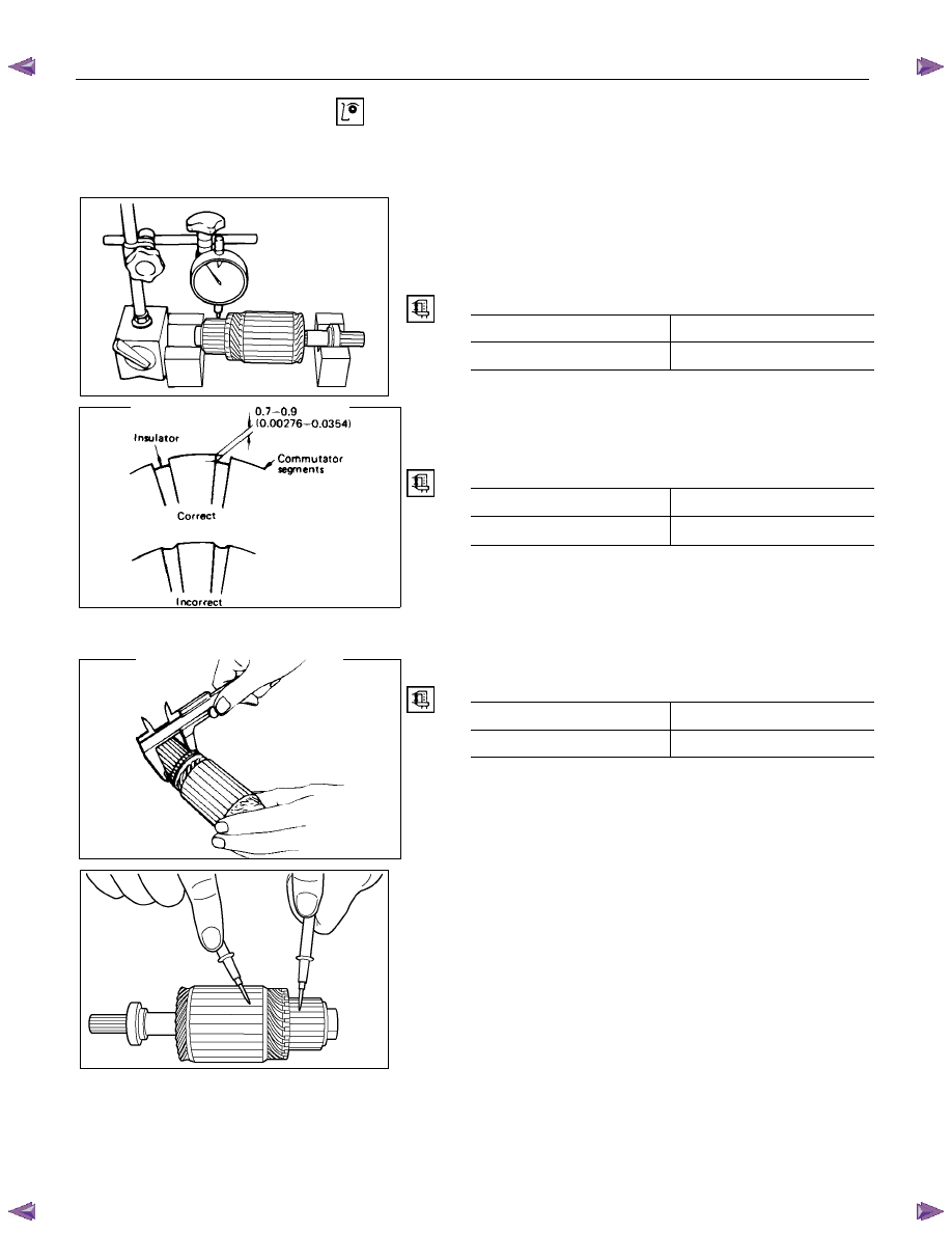
1. Measure the commutator run-out.
Replace the commutator if the measured run-out
exceeds the specified limit.
Commutator Run-Out
mm (in)
Standard Limit
0.05 (0.002)
0.2 (0.008)
RTW46DSH003501
2. Check the commutator mica segments for excessive
wear.
3. Measure the mica segment depth.
Mica Segment Depth
mm (in)
Standard Limit
0.5
∼ 0.8 (0.020 ∼ 0.030)
0.2 (0.008)
065RY00025
If the mica segment depth is less than the standard but
more than the limit, the commutator may be reground.
If the mica segment depth is less than the limit, the
commutator must be replaced.
4. Measure the commutator outside diameter.
Commutator Outside Diameter
mm (in)
Standard Limit
36.5 (1.44)
35.5 (1.40)
If the measured outside diameter is less than the specified
limit, the commutator must be replaced.
065RY00026
RTW46DSH003601
5. Use a circuit tester to check the armature for
grounding.
1
Hold one probe of the circuit tester against the
commutator segment.
2
Hold the other circuit tester probe against the
armature core.
If the circuit tester indicates continuity, the armature is
grounded.
The armature must be replaced.
Нет комментариевНе стесняйтесь поделиться с нами вашим ценным мнением.
Текст