Isuzu KB P190. Manual — part 811
Engine Management – V6 – General Information
Page 6C1-1–2
3.9
Serial Data Communication System. . . . . . . . . . . . . . . . . . . . . . . . . . . . ... 17
3.10
Self Diagnostics System . . . . . . . . . . . . . . . . . . . . . . . . . . . . . . . . . . 17
3.11
Service Programming System . . . . . . . . . . . . . . . . . . . . . . . . . . . . . . . 17
3.12
Immobiliser System . . . . . . . . . . . . . . . . . . . . . . . . . . . . . . . . . . . . 18
4
Component Description and Operation . . . . . . . . . . . . . . . . . . . . . . . .19
4.1
A/C Refrigerant Pressure Sensor . . . . . . . . . . . . . . . . . . . . . . . . . . . . . ... 19
4.2
Brake Pedal Switch Assembly . . . . . . . . . . . . . . . . . . . . . . . . . . . . . . . 19
Stop Lamp and Initial Brake Apply Switch . . . . . . . . . . . . . . . . . . . . . . . . . . 19
Stop Lamp Switch . . . . . . . . . . . . . . . . . . . . . . . . . . . . . . . . . . . 19
Initial Brake Apply Switch . . . . . . . . . . . . . . . . . . . . . . . . . . . . . . . . . 19
4.3
Barometric Pressure Sensor. . . . . . . . . . . . . . . . . . . . . . . . . . . . . . . ... 20
4.4
Camshaft Position Sensor . . . . . . . . . . . . . . . . . . . . . . . . . . . . . . . . .. 20
4.5
Crankshaft Position Sensor . . . . . . . . . . . . . . . . . . . . . . . . . . . . . . . . 21
4.6
Clutch Pedal Switch Assembly – Manual Vehicles Only . . . . . . . . . . . . . . . . . . . . .. 22
4.7
Engine Control Module. . . . . . . . . . . . . . . . . . . . . . . . . . . . . . . . . . 22
4.8
Engine Coolant Temperature Sensor. . . . . . . . . . . . . . . . . . . . . . . . . . . . . 23
4.9
Electric Cooling Fans . . . . . . . . . . . . . . . . . . . . . . . . . . . . . . . . . . .. 23
4.10
Engine Oil Level and Temperature Sensor . . . . . . . . . . . . . . . . . . . . . . . . . . 24
Engine Oil Temperature Sensor . . . . . . . . . . . . . . . . . . . . . . . . . . . . . . . 24
Engine Oil Level Sensor. . . . . . . . . . . . . . . . . . . . . . . . . . . . . . . . . .. 25
4.11
Engine Oil Pressure Sensor. . . . . . . . . . . . . . . . . . . . . . . . . . . . . . . . 25
4.12
Fuel Injectors. . . . . . . . . . . . . . . . . . . . . . . . . . . . . . . . . . . . . . 26
4.13
Fuel Rail Assembly . . . . . . . . . . . . . . . . . . . . . . . . . . . . . . . . . . . .. 27
4.14
Heated Oxygen Sensors. . . . . . . . . . . . . . . . . . . . . . . . . . . . . . . . . .. 27
LSF 4.2 Two-step Planar Heated Oxygen Sensors . . . . . . . . . . . . . . . . . . . . . . ... 27
LSU 4.2 Wide-band Planar Heated Oxygen Sensors . . . . . . . . . . . . . . . . . . . . . . 29
4.15
Ignition Coil and Spark Plug . . . . . . . . . . . . . . . . . . . . . . . . . . . . . . . ... 31
4.16
Intake Air Temperature Sensor. . . . . . . . . . . . . . . . . . . . . . . . . . . . . . ... 32
4.17
Knock Sensor. . . . . . . . . . . . . . . . . . . . . . . . . . . . . . . . . . . . . ... 32
4.18
Mass Air Flow Sensor. . . . . . . . . . . . . . . . . . . . . . . . . . . . . . . . . . .. 33
Air Intake System . . . . . . . . . . . . . . . . . . . . . . . . . . . . . . . . . . . . . 33
Mass Air Flow Sensor. . . . . . . . . . . . . . . . . . . . . . . . . . . . . . . . . . .. 33
Construction . . . . . . . . . . . . . . . . . . . . . . . . . . . . . . . . . . . . . . 34
Operation . . . . . . . . . . . . . . . . . . . . . . . . . . . . . . . . . . . . . . . 34
5
Abbreviations and Glossary of Terms . . . . . . . . . . . . . . . . . . . . . . . ...35

Engine Management – V6 – General Information
Page 6C1-1–3
1 General
Information
The V6 engine management system
incorporates functions and components that
could cause personal injury or vehicle
damage. Refer to 6C1-2 Engine Management –
V6 – Diagnostics, and 6C1-3 Engine
Management – V6 – Service Operations,
before attempting any diagnosis or repairs.
1.1 Introduction
The V6 engine management system is designed to improve engine performance and increase vehicle safety while
meeting the stringent Euro 3 vehicle emission standard. This is achieved by the introduction of the following engine
management sub-systems and components:
•
Throttle actuator control (TAC) System – the TAC system allows the engine control module (ECM) to electronically
control the throttle plate opening eliminating the need for the following components:
•
mechanical link between the throttle plate and accelerator pedal,
•
cruise control module, and
•
idle air control motor.
Refer to 3.5 Throttle Actuator Control System for details of the TAC System operation and to 3.6
Cruise
Control System for details of the cruise control operation.
This feature results in improved driveability, better fuel economy and emission control.
•
Wide band heated oxygen sensor provides a more accurate measurement of the oxygen concentration in the
exhaust gas. Refer to 4.14
Heated Oxygen Sensors.
•
Dual spray fuel injectors are now used. The use of this spray pattern is used in engines with two intake valves per
cylinder. The dual spray is achieved by having two openings in the spray orifice disc that are arranged in such a
way that two fuel sprays result, being aimed at each intake valve port. Refer to 4.12 Fuel Injectors.
•
Pencil Coil – allows the ignition coil to be fitted directly on the spark plug eliminating the need for spark plug wires.
Refer to 4.15
Ignition Coil and Spark Plug.
The engine management system has a self diagnostic capability, as well as connections to enable diagnosis of faults. If
the ECM recognises operational problems it can alert the driver via the malfunction indicator lamp (MIL) in the instrument
cluster. The ECM also interfaces with other systems in the vehicle as required.
For further information on the air-conditioning system refer to 2A Heater and Air-conditioning,
For the location of fuses, fusible links and relays, refer to 8A Electrical-Body and Chassis.
1.2 Emission
Control
ADR 79/01 Emissions Standards
MY2006 I190 Rodeo has been configured to comply with Australian Design Rule 79/01, that adopts the technical
requirements of the European Council Directive 98/69/EC. Commonly referred to as “Euro 3”, the new legislation
modifies the exhaust emissions, compared to the existing ADR 37/01 (or ‘Euro 2’) vehicle emissions standards.
Australian Design Rule 79/01 implements the 'Euro 3' exhaust and evaporative emissions requirements for petrol fuelled
passenger cars, forward control vehicles and passenger off-road vehicles with a gross vehicle mass (GVM) up to 3.5
tonnes. All new vehicles within these categories and first registered from January 1, 2006 must comply with ADR 79/01.
The next table shows a comparison between the existing ADR 37/01 (‘Euro 2’) and ADR 79/01 (‘Euro 3’)
Hydrocarbons
Carbon
Monoxide (g/km)
Exhaust
(g/km)
Evaporative
(g/test)
Oxides of Nitrogen
(g/km)
Particulate
Matter (g/test)

Engine Management – V6 – General Information
Page 6C1-1–4
ADR 37/01 (Petrol)
2.1
0.26
2
0.63
Not Applicable
ADR 79/01 (Petrol,
LPG, CNG)
2.3 0.2
2
0.15
0.05
1.3
Warning Caution and Notes
This Section contains various WARNINGS, CAUTIONS and NOTE statements that you must observe carefully to reduce
the risk of death or injury during service, repair procedures or vehicle operation. Incorrect service or repair procedures
may damage the vehicle or cause operational faults. WARNINGS, CAUTION and NOTE statements are not exhaustive.
GM Holden LTD can not possibly warn of all the potentially hazardous consequences of failure to follow these
instructions.
Definition of WARNING, CAUTION and NOTE Statements
Diagnosis and repair procedures in this Section contain both general and specific WARNING, CAUTION and NOTE
statements. GM Holden LTD is dedicated to the presentation of service information that helps the technician to diagnose
and repair the systems necessary for proper operation of the vehicle. Certain procedures may present a hazard to the
technician if they are not followed in the recommended manner. WARNING, CAUTION and NOTE statements are
designed to help prevent these hazards from occurring, but not all hazards can be foreseen.
WARNING defined
A WARNING statement immediately precedes an operating procedure or maintenance practice which, if not correctly
followed, could result in death or injury. A WARNING statement alerts you to take necessary action or not to take a
prohibited action. If a WARNING statement is ignored, the following consequences may occur:
•
Death or injury to the technician or other personnel working on the vehicle,
•
Death or injury to other people in or near the workplace area, and / or
•
Death or injury to the driver / or passenger(s) of the vehicle or other people, if the vehicle has been improperly
repaired.
CAUTION defined
A CAUTION statement immediately precedes an operating procedure or maintenance practice which, if not correctly
followed, could result in damage to or destruction of equipment, or corruption of data. If a CAUTION statement is ignored,
the following consequences may occur:
•
Damage to the vehicle,
•
Unnecessary vehicle repairs or component replacement,
•
Faulty operation or performance of any system or component being repaired,
•
Damage to any system or components which depend on the proper operation of the system or component being
repaired,
•
Faulty operation or performance of any systems or components which depend on the proper operation or
performance of the system or component under repair,
•
Damage to fasteners, basic tools or special tools and / or
•
Leakage of coolant, lubricant or other vital fluids.
NOTE defined
A NOTE statement immediately precedes or follows an operating procedure, maintenance practice or condition that
requires highlighting. A NOTE statement also emphasises necessary characteristics of a diagnostic or repair procedure.
A NOTE statement is designed to:
•
Clarify a procedure,
•
Present additional information for accomplishing a procedure,
•
Give insight into the reasons for performing a procedure in the recommended manner, and / or
•
Present information that gives the technician the benefit of past experience in accomplishing a procedure with
greater ease.
Engine Management – V6 – General Information
Page 6C1-1–5
2 Component
Locations
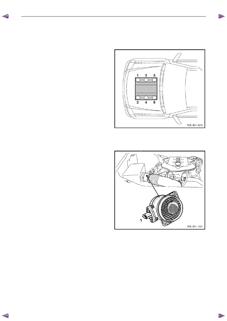
2.1 Cylinder
Numbering
Engine cylinder identification follows the international
standard OBD II. This standard calls for the engine cylinder
bank number one to be identified by the location of cylinder
number one. Therefore the numbering for the V6 engine is:
The V6 engine cylinders are numbered as follows:
•
1, 3, 5 – Right-hand side (Bank 1),
•
2, 4, 6 – Left-hand side (Bank 2).
The engine firing order is 1, 2, 3, 4, 5, 6.
Figure 6C1-1 – 1
2.2 Engine
Compartment
Legend
1
Mass Air Flow (MAF) Sensor
2
Air-conditioner Refrigerant Pressure Sensor
Figure 6C1-1 – 2
Нет комментариевНе стесняйтесь поделиться с нами вашим ценным мнением.
Текст