Isuzu KB P190. Manual — part 809

Fuel System – V6
Page 6C – 34
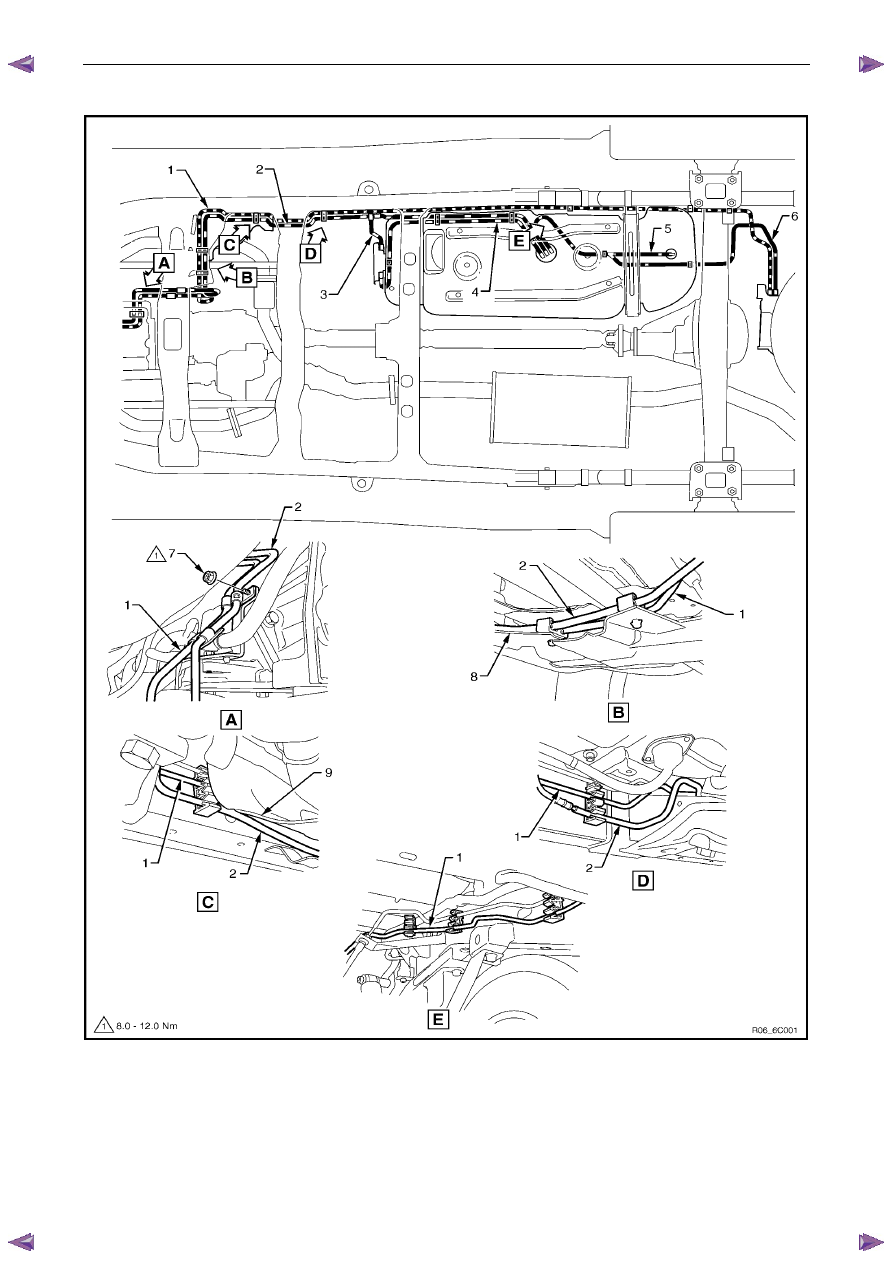
Fuel Tank Lines
Figure 6C – 38
Legend
1
Fuel Feed Line
2
Fuel Return Line
3
Fuel Vapour emission port
4
Fuel Pump and Sender Assembly
5
Connector; Fuel Pump and Sender
6 Fuel
Lines
7
Retainer Ring (Fuel Pump Lock)
8
“O” Ring Seal
9
Fuel Tank Assembly
10
Fuel Vapour Vent Line
Reinstall
Ensure the plastic fuel line clips are in good
condition before proceeding. If not, replace
the defective clips.
Reinstallation of the stone guard and fuel lines is the reverse of the removal procedure, noting the following:
1
Tighten the Fuel line securing nut to the correct torque specification, refer to Figure 6C – 39.
Fuel line securing nut
torque specification . . . . . . . . . . .8 – 12 Nm
2
Tighten the stone guard securing bolts to the correct torque specification.
Stone guard securing bolt
torque specification . . . . . . . . . .5.0 – 7.0 Nm
Fuel System – V6
Page 6C – 35
Fuel Line Routing
Figure 6C – 39
Legend
1
Evaporative Emission Control
Canister Purge Line
2
Fuel Feed Line
3
Fuel Line From Fuel Filter
4
Fuel Feed Line To Fuel Filter
5
Evaporative Line To Rollover Valve
6
Evaporative Line To Canister
7
Fuel Line Securing Nut
8 Stone
Guard
9
Side Stone Guard

Fuel System – V6
Page 6C – 36
Bell Housing Fuel Lines
1
Remove the bolt (1) securing the fuel line bracket to
the upper left-hand side of the bell housing, refer to
7B1 Transmission.
N O T E
The left-hand front exhaust pipe may need to be
moved aside to gain access to the fuel line
retaining bracket bolt (1), refer to 6F Exhaust
System – V6.
Fuel line bracket bolt
torque specification . . . . . . . . ...8.0 – 12.0 Nm
Figure 6C – 40
Engine Bay Fuel Lines
1
Remove the nut (5) from the fuel line bracket (4).
2
Unclip the fuel lines from the engine, refer to 4.1 Fuel
Lines And Quick Connect Fittings.
Figure 6C – 41
Fuel System – V6
Page 6C – 37
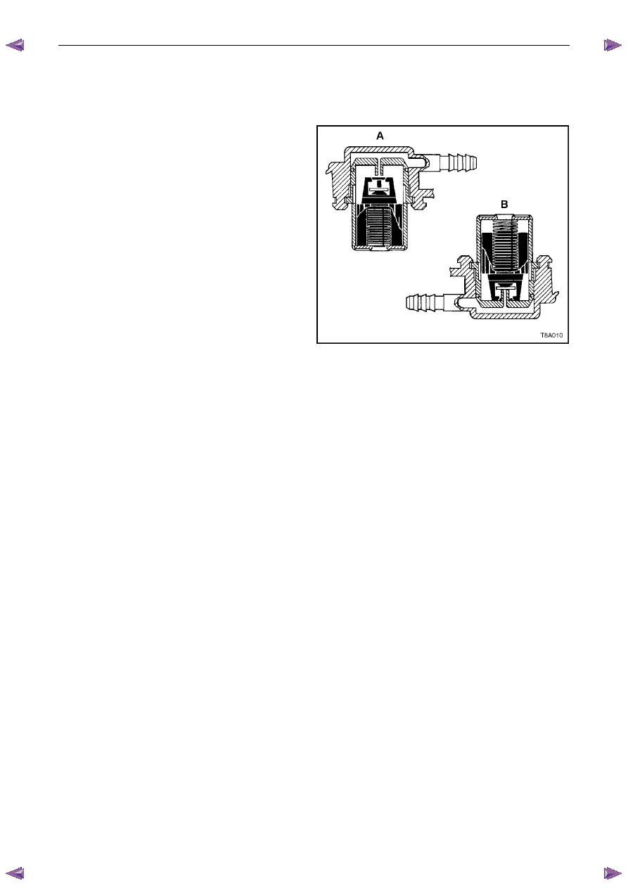
4.10 Rollover
Valve
The fuel tank incorporates two rollover valves. The rollover
valve limits vapour venting to the evaporative emission
control canister using a fixed-sized orifice that is normally
open (View A). If the vehicle rolls over (View B), the fuel
tank vent line to the evaporative emission control canister is
safely shut off by the rollover valve, preventing liquid fuel
from flooding the evaporative emission control canister.
N O T E
The rollover valve is welded to the top of the fuel
tank and is not a serviceable item. If the rollover
valve becomes unserviceable, the fuel tank must
be replaced, refer to 4.4
Fuel Tank.
Figure 6C – 42
Нет комментариевНе стесняйтесь поделиться с нами вашим ценным мнением.
Текст