Isuzu KB P190. Manual — part 1235

8A-2 ELECTRICAL-BODY AND CHASSIS
PAGE
Fuse Block Circuit (4JJ1-TC/4JK1-TC (RHD)) SOUTH AFRICA . . . . . . . ...8A- 39
Fuse Block Circuit (4JJ1-TC/4JK1-TC (RHD)) EXCEPT SOUTH AFRICA . . . ...8A- 41
Fuse Block Circuit (4JJ1-TC/4JK1-TC) - (LHD) G.EXP . . . . . . . . . . . .8A- 43
Fuse Block Circuit (4JH1-TC) - (LHD) . . . . . . . . . . . . . . . . . . 8A- 45
Fuse Block Circuit (4JA1T (L)) . . . . . . . . . . . . . . . . . . . . ...8A- 47
Grounding Point . . . . . . . . . . . . . . . . . . . . . . . . . . . ..8A- 49
Ground Point . . . . . . . . . . . . . . . . . . . . . . . . . . . ...8A- 49
Ground Point Location . . . . . . . . . . . . . . . . . . . . . . . ...8A- 89
Cable Harness Routing . . . . . . . . . . . . . . . . . . . . . . . . ...8A- 91
Main Cable Harness (RHD). . . . . . . . . . . . . . . . . . . . . . ..8A- 91
Instrument Harness (RHD) . . . . . . . . . . . . . . . . . . . . . . ..8A- 92
Main Cable Harness (LHD) . . . . . . . . . . . . . . . . . . . . . . ..8A- 93
Instrument Harness (LHD) . . . . . . . . . . . . . . . . . . . . . . ..8A- 94
Engine Harness C24SE . . . . . . . . . . . . . . . . . . . . . . . ...8A- 95
Engine Harness 4JJ1-TC/4JK1-TC . . . . . . . . . . . . . . . . . . . 8A- 96
Engine Harness 4JH1-TC/4JA1T (L) . . . . . . . . . . . . . . . . . . ...8A- 97
Transmission Harness . . . . . . . . . . . . . . . . . . . . . . . ...8A- 98
System Repair . . . . . . . . . . . . . . . . . . . . . . . . . . . . ..8A- 100
Start and Charging . . . . . . . . . . . . . . . . . . . . . . . . . ..8A- 100
Engine Control Module (ECM) . . . . . . . . . . . . . . . . . . . . ...8A- 111
Exhaust Gas Recirculation (EGR) & GLOW; 4JA1T (L) Only . . . . . . . . ...8A- 143
Lighting . . . . . . . . . . . . . . . . . . . . . . . . . . . . . . 8A- 149
Front Fog Light . . . . . . . . . . . . . . . . . . . . . . . . . . ...8A- 180
Rear Fog Light . . . . . . . . . . . . . . . . . . . . . . . . . . . 8A- 190
Headlight Leveling . . . . . . . . . . . . . . . . . . . . . . . . . ..8A- 194
Illumination . . . . . . . . . . . . . . . . . . . . . . . . . . . . ..8A- 200
Hazard Warning Flasher, Turn Signal Light, Backup Light,
Horn and Stoplight . . . . . . . . . . . . . . . . . . . . . . . . . 8A- 213
Dome Light, Spotlight, Map Light and Warning Buzzer . . . . . . . . . . ..8A- 245
Windshield Wiper and Washer . . . . . . . . . . . . . . . . . . . . ..8A- 264
Transmission Control Module (TCM) . . . . . . . . . . . . . . . . . . 8A- 285
Manual Transmission Shift Assist . . . . . . . . . . . . . . . . . . . .8A- 298
Meter, Warning Light and Indicator Light . . . . . . . . . . . . . . . . .8A- 303
Heater and Air Conditioning . . . . . . . . . . . . . . . . . . . . . ..8A- 371
Power Door Lock . . . . . . . . . . . . . . . . . . . . . . . . . . 8A- 386

ELECTRICAL-BODY AND CHASSIS 8A-3
PAGE
Power Window . . . . . . . . . . . . . . . . . . . . . . . . . . . 8A- 415
Audio, Clock and Cigarette Lighter . . . . . . . . . . . . . . . . . . ...8A- 440
Power Door Mirror . . . . . . . . . . . . . . . . . . . . . . . . . ..8A- 464
Rear Defogger . . . . . . . . . . . . . . . . . . . . . . . . . . . .8A- 480
Supplemental Restraint System (SRS)-Air Bag . . . . . . . . . . . . . . 8A- 491
Transfer Case Control Module . . . . . . . . . . . . . . . . . . . . ...8A- 498
Anti-Lock Brake System . . . . . . . . . . . . . . . . . . . . . . . .8A- 514
Immobilizer . . . . . . . . . . . . . . . . . . . . . . . . . . . . ..8A- 519
Keyless Entry . . . . . . . . . . . . . . . . . . . . . . . . . . . ..8A- 529
Data Link Connector . . . . . . . . . . . . . . . . . . . . . . . . ...8A- 553
Anti Theft . . . . . . . . . . . . . . . . . . . . . . . . . . . . . ..8A- 561
Key Inter Lock . . . . . . . . . . . . . . . . . . . . . . . . . . . .8A- 588
DRM . . . . . . . . . . . . . . . . . . . . . . . . . . . . . . . ..8A- 592
Trailer Hitch . . . . . . . . . . . . . . . . . . . . . . . . . . . . .8A- 595
Power Train Interface Module (PIM) . . . . . . . . . . . . . . . . . . ..8A- 600
Connector List . . . . . . . . . . . . . . . . . . . . . . . . . . . . .8A- 606

8A-4 ELECTRICAL-BODY AND CHASSIS
GENERAL INFORMATION
The body and chassis electrical system operates on a twelve volt power supply with negative ground polarity.
The main harness consists of the engine harness, the instrument harness, the body harness, and the chassis
harness.
The harnesses use a split corrugated tube to protect the wires from the elements.
Wire size is determined by current flow, circuit length, and voltage drop.
All wires have color-coded insulation.
Wire color-codes are shown in the circuit diagrams.
This makes it easier to trace circuits and to make the proper connections.
Each circuit consists of the following:
5. Power source – The battery and the alternator
5. Wires – To carry electrical current through the circuit
5. Fuses – To protect the circuit against current overload
5. Relays – To protect voltage drop between the battery and the circuit parts and to protect the switch points
against burning
5. Switches – To open and close the circuit
5. Load – Any device, such as a light or motor, which converts the electrical current into useful work
5. Ground – To allow the current to flow back to the power source
ELECTRICAL-BODY AND CHASSIS 8A-5
NOTES FOR WORKING ON ELECTRICAL ITEMS
Battery
BATTERY CABLE
Disconnecting the Battery Cable
5. All switches should be “OFF” position.
5. Disconnect the battery ground cable.
5. Disconnect the battery positive cable.
CAUTION:
It is important that the battery ground cable be
disconnected first.
Disconnecting the battery positive cable first can result in
a short circuit.
Connecting the Battery Cable
Follow the disconnecting procedure in the reverse order to
connect the battery cables.
CAUTION:
Clean the battery terminal and apply light coat of grease to
prevent terminal corrosion.
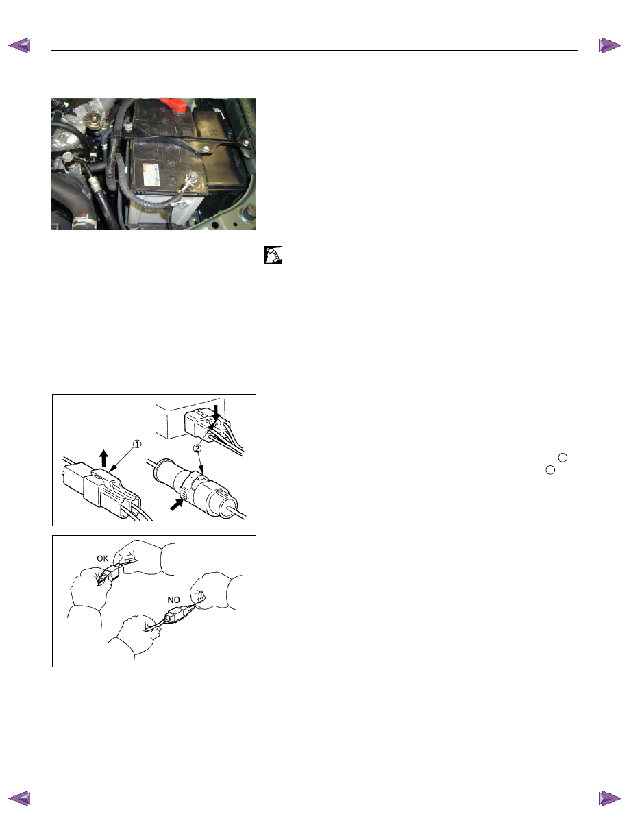
CONNECTOR HANDLING
Disconnecting the Connectors
Some connectors have a tang lock to hold the connectors
together during vehicle operation.
Some tang locks are released by pulling them towards you
1
.
Other tang locks are released by pressing them forward
2
.
Determine which type of tang lock is on the connector being
handled.
Firmly grasp both sides (male and female) of the connector.
Release the tang lock and carefully pull the two halves of the
connector apart.
Never pull on the wires to separate the connectors.
This will result in wire breakage.
Нет комментариевНе стесняйтесь поделиться с нами вашим ценным мнением.
Текст