Isuzu KB P190. Manual — part 743

Engine Mechanical – V6
Page 6A1–195
Page 6A1–195
11
Ensure that the feet (2) of the Tool No. EN 48313 are
facing the front of the engine.
CAUTION
DO NOT tighten the Tool No. EN 48313 at
this stage.
12
Partially expand the legs (1) on the Tool No. EN
48313 by turning the T-shaped handle clockwise.
CAUTION
Ensure the feet (2) of the Tool No. EN 48313
are correctly engaged into one of the link
pockets to prevent the chain from slipping
during tightening.
13
Continue expanding the Tool No. EN 48313 until the
feet (2) contact the timing chain.
Figure 6A1 – 316
14
Hand tighten the Tool No. EN 48313. DO NOT allow the body of the Tool No. EN 48313 to rotate when tightening
the T-handle.
15
Use an open-end spanner on the hex cast into both the right intake and exhaust camshafts and rotate the
camshafts towards each other in order to create slack in the chain between the actuators.
16
The Tool No. EN 48313 is now correctly installed to hold the timing chain in position.
N O T E
Ensure the camshaft timing chain and the
camshaft position actuators are marked for
correct reassembly.
17
Mark the timing chain and the respective location on both camshaft position actuators.
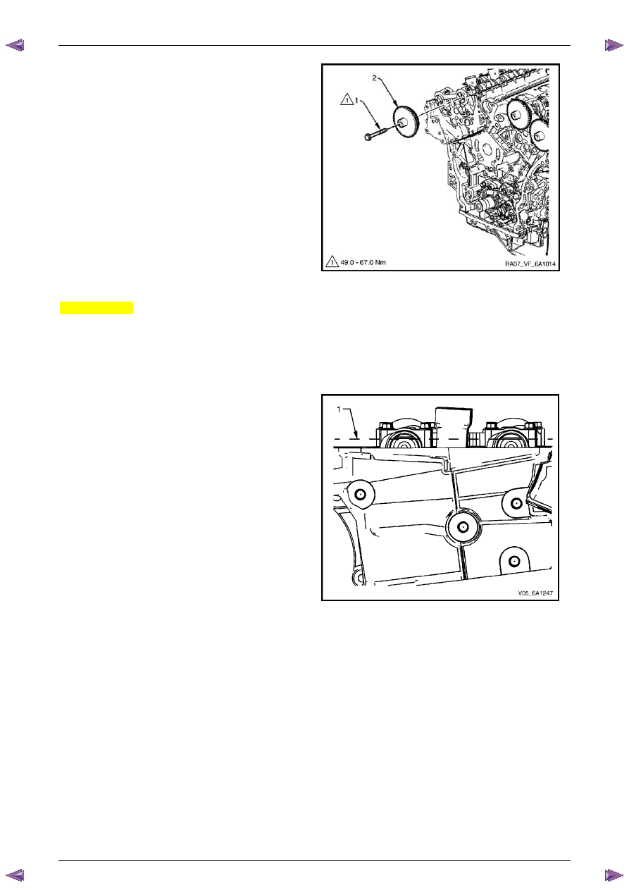
18
Remove the bolt (1) attaching the right-hand exhaust
camshaft sprocket (2) and remove the sprocket.
Figure 6A1 – 317
Engine Mechanical – V6
Page 6A1–196
Page 6A1–196
19
Remove the bolt (1) attaching right-hand intake
camshaft sprocket (2) and remove the sprocket.
Figure 6A1 – 318
Left-hand Side
1
Remove the left-hand camshaft cover, refer to
3.12 Camshaft Cover
.
2
Remove the camshaft position sensors, refer to
Section 6C1-3 Engine Management – V6 – Service Operations
.
3
Remove the camshaft position actuator solenoids, refer to
Section 6C1-3 Engine Management – V6 – Service
Operations
.
4
Remove the crankshaft balancer assembly, refer to
3.13 Crankshaft Balancer Assembly
.
5
Install the crankshaft rotation socket Tool No.
EN-46111 onto the crankshaft.
6
Rotate the crankshaft until the camshafts are in a
neutral low tension position. The camshaft flats will be
parallel with the camshaft cover rail (1).
Figure 6A1 – 319

Engine Mechanical – V6
Page 6A1–197
Page 6A1–197
7
Install Tool No. EN-46105–1 (1) onto the rear of the
left-hand cylinder head camshafts (2).
Figure 6A1 – 320
N O T E
Use an open-end wrench (1) at the camshaft
hex (2) to prevent camshaft/engine rotation.
N O T E
Do not remove the camshaft sprocket bolt (3) at
this time.
8
Loosen the camshaft sprocket bolt (3).
N O T E
If the camshaft timing chain has already been
removed proceed to Step 12.
Figure 6A1 – 321
N O T E
The front engine cover is removed in the
following graphic for illustration purposes and is
not required to be removed to perform this
procedure.
9
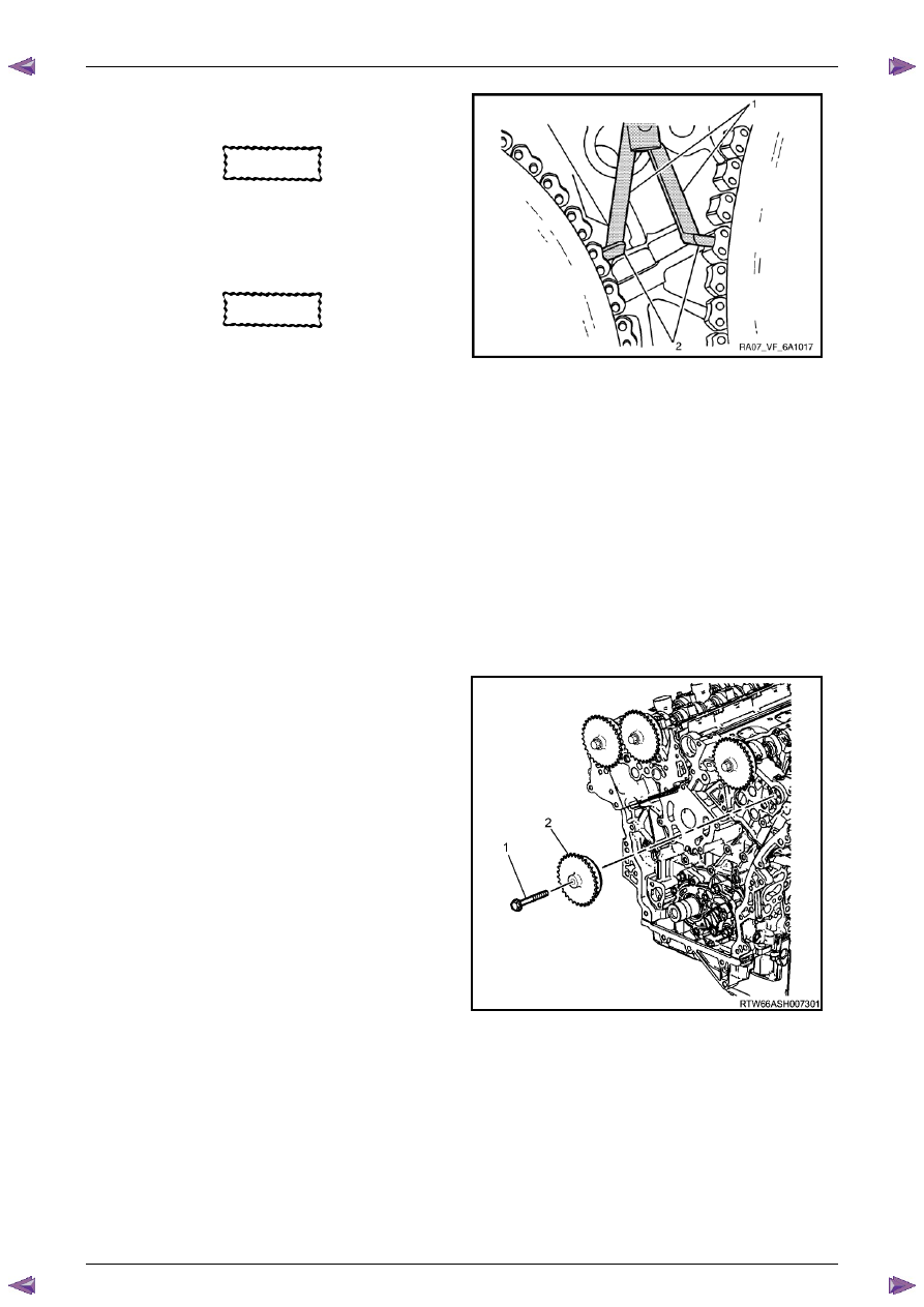
Loosen the timing chain retention Tool No. EN 48313
so that the legs are retracted.
10
Insert the Tool No. EN 48313 between the camshaft
actuators, rearward of the timing chain until the top
line that is scribed into the body of the tool (1) is
adjacent to the top surface of the cylinder head (2).
This is the approximate installed position.
Figure 6A1 – 322
Engine Mechanical – V6
Page 6A1–198
Page 6A1–198
11
Ensure that the feet (2) of the Tool No. EN 48313 are
facing the front of the engine.
CAUTION
DO NOT tighten the Tool No. EN 48313 at
this stage.
12
Partially expand the legs (1) on the Tool No. EN
48313 by turning the T-shaped handle clockwise.
CAUTION
Ensure the feet (2) of the Tool No. EN 48313
are correctly engaged into one of the link
pockets to prevent the chain from slipping
during tightening.
Figure 6A1 – 323
13
Continue expanding the Tool No. EN 48313 until the feet (2) contact the timing chain.
14
Hand tighten the Tool No. EN 48313. DO NOT allow the body of the Tool No. EN 48313 to rotate when tightening
the T-handle.
15
Use an open-end spanner on the hex cast into both the left intake and exhaust camshafts and rotate the camshafts
towards each other in order create slack in the chain between the actuators.
16
The Tool No. EN 48313 is now correctly installed to hold the timing chain in position.
N O T E
Ensure the camshaft timing chain and the
camshaft position actuators are marked for
correct reassembly.
17
Mark the timing chain and the respective location on both camshaft position actuators.
18
Remove the bolt (1) attaching the left-hand exhaust
camshaft sprocket (2) and remove the sprocket.
Figure 6A1 – 324
Нет комментариевНе стесняйтесь поделиться с нами вашим ценным мнением.
Текст