Isuzu KB P190. Manual — part 742

Engine Mechanical – V6
Page 6A1–191
Page 6A1–191
13
Remove the bolt (1) attaching left-hand intake
camshaft sprocket (2) and remove the sprocket.
Figure 6A1 – 309
Clean
1
Clean the exterior of each camshaft sprocket with solvent.
Safety glasses must be worn when using
compressed air.
2
Dry the timing components with compressed air.
Inspect
1
Inspect the front of each sprocket for the following:
•
Sprocket damage (1), and
•
Sprocket bolt seating inner hub damage (2).
Figure 6A1 – 310
Engine Mechanical – V6
Page 6A1–192
Page 6A1–192
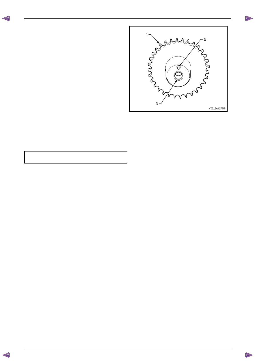
2
Inspect the back of each sprocket for the following:
•
Sprocket damage (1),
•
Camshaft locating pin damage (2) and,
•
Camshaft seating/sealing inner hub flange
damage (3),
N O T E
These checks apply to both the inlet and
exhaust camshaft sprockets.
Figure 6A1 – 311
Reinstall
Reinstallation of the camshaft sprockets is the reverse of the removal procedure, noting the following:
1
Align the sprockets and timing chain with the marks made during removal.
2
Tighten the camshaft sprocket bolts to the correct torque specification.
Camshaft sprocket attaching
bolt torque specification . . . . . . ..49.0 – 67.0 Nm
3
Remove the timing chain retention tools.
Engine Mechanical – V6
Page 6A1–193
Page 6A1–193
3.19 Camshaft Sprocket – MY06 Update
CAUTION
Setting the camshaft timing is required
whenever the camshaft drive system is
disturbed to ensure the relationship between
any chain and sprocket is not lost. Even when
only one sprocket is involved, multiple
crankshaft rotations will not produce
conditions where correct timing can be
confirmed.
If required, follow the Left-hand Secondary
Camshaft Chain Components reinstallation
procedure to reset the camshaft timing.
Remove
Right-hand Side
1
Remove the right-hand camshaft cover, refer to
3.12 Camshaft Cover
.
2
Remove the camshaft position sensors, refer to
Section 6C1-3 Engine Management – Service Operations
.
3
Remove the camshaft position actuator solenoids, refer to
Section 6C1-3 Engine Management – V6 – Service
Operations
.
4
Remove the crankshaft balancer assembly, refer to
3.13 Crankshaft Balancer Assembly
.
5
Install the crankshaft rotation socket Tool No.
EN-46111 onto the crankshaft.
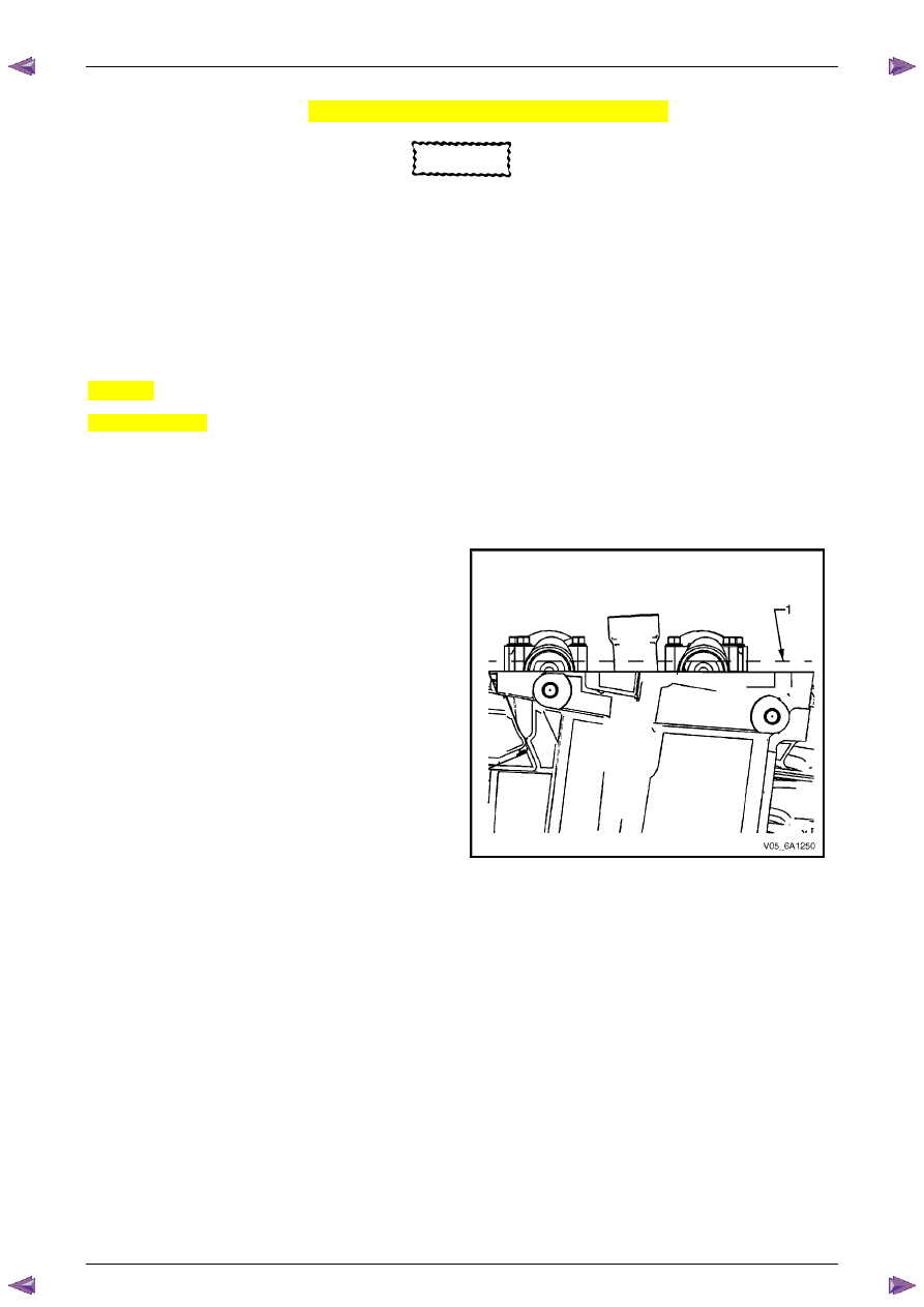
6
Rotate the crankshaft until the camshafts are in a
neutral low tension position. The camshaft flats will be
parallel with the camshaft cover rail (1).
Figure 6A1 – 312
Engine Mechanical – V6
Page 6A1–194
Page 6A1–194
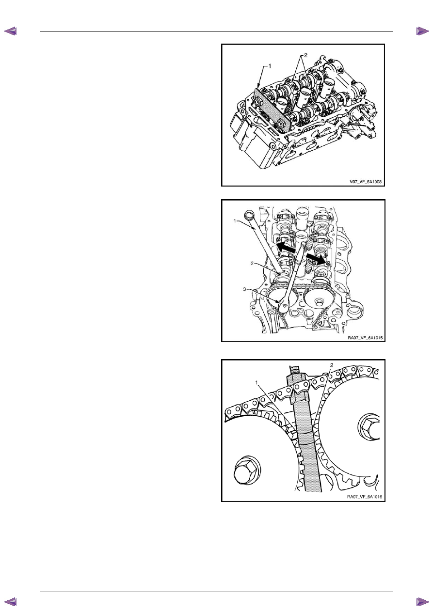
7
Install Tool No. EN-46105–1 (1) onto the rear of the
right-hand cylinder head (3) camshafts (2).
Figure 6A1 – 313
N O T E
Use an open-end spanner (1) at the camshaft
hex (2) to prevent camshaft/engine rotation.
N O T E
Do not remove the camshaft sprocket bolt (3) at
this time.
8
Loosen the camshaft sprocket bolt (3).
N O T E
If you have already removed the camshaft
timing chain proceed to Step 12
Figure 6A1 – 314
N O T E
The front engine cover is removed in the
following graphic for illustration purposes and is
not required to be removed to perform this
procedure.
9
Loosen the timing chain retention Tool No. EN 48313
so that the legs are retracted.
10
Insert the Tool No. EN 48313 between the camshaft
actuators, rearward of the timing chain until the top
line that is scribed into the body of the tool (1) is
adjacent to the top surface of the cylinder head (2).
This is the approximate installed position.
Figure 6A1 – 315
Нет комментариевНе стесняйтесь поделиться с нами вашим ценным мнением.
Текст