Isuzu KB P190. Manual — part 188
BRAKES 5C-53
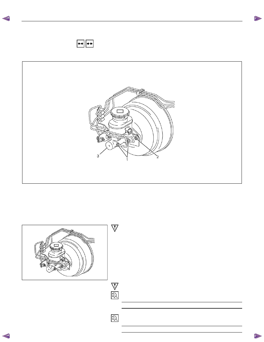
MASTER CYLINDER
REMOVAL AND INSTALLATION
MASTER CYLINDER ASSEMBLY
This illustration is based on the RHD model
RTW75CMF000901
Removal Steps
▲ 1. Brake line
2. Nut; Master cylinder to vacuum booster
3. Master cylinder assembly
Installation Steps
3. Master cylinder assembly
▲ 2. Nut; Master cylinder to vacuum booster
▲ 1. Brake line
RTW75CSH002701
Important Operation - Removal
1. Brake Line
Be very careful not to spill brake fluid on the painted surface.
Damage to the painted surface will result.
Important Operation - Installation
2. Nut; Master Cylinder to Vacuum Booster
Torque N
⋅m (kgf⋅m/lb⋅ft)
10 – 16 (1.0 – 1.6 / 7 – 12)
1. Brake Line
Torque N
⋅m (kgf⋅m/lb⋅ft)
13 – 19 (1.3 – 1.9 / 9 – 14)
5C-54 BRAKES
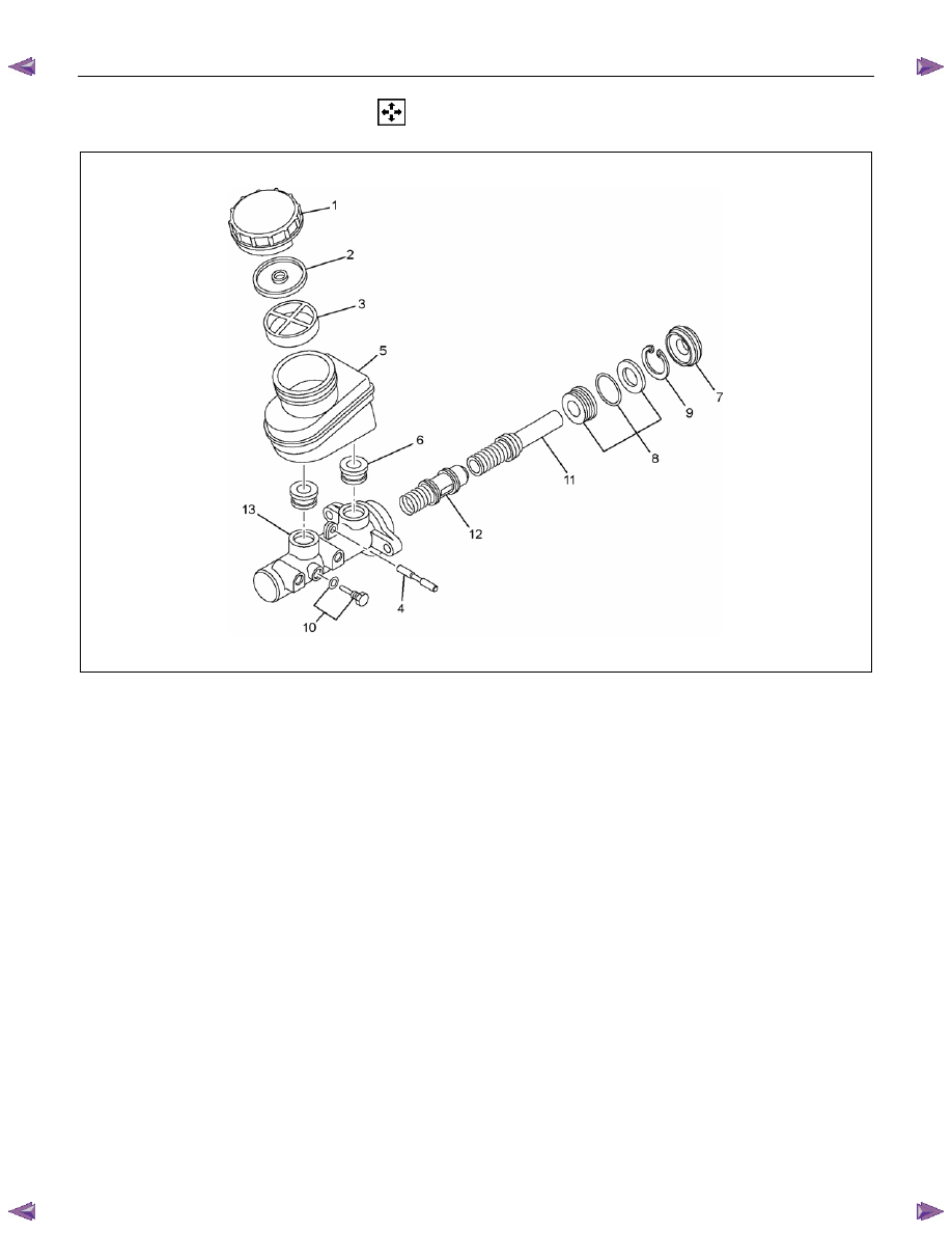
DISASSEMBLY
RTW75CMF000701
Disassembly Steps
1.
Cap
2.
Diaphragm
3.
Filter
4.
Pin
5. Reservoir tank
6.
Grommet
▲ 7. Front seal
8. Guide assembly
▲ 9. Snap ring
▲10. Stopper bolt and gasket
▲11. Primary piston
▲12. Secondary piston
13. Cylinder body
Note:
• Be sure to replace the designated with new ones.
• Wash the disassembled parts in clean brake fluid.
• Use compressed air to clean the ports.
• Do not allow dirt and dust to contaminate the disassembled
parts.
BRAKES 5C-55
Important Operations
When disassembling, inspecting or reassembling the master
cylinder assembly, take care not to bring the parts into contact
with mineral oil or dust. Wash the piston cups only with brake
fluid. Do not use gasoline or other mineral-base cleaning
solvents.
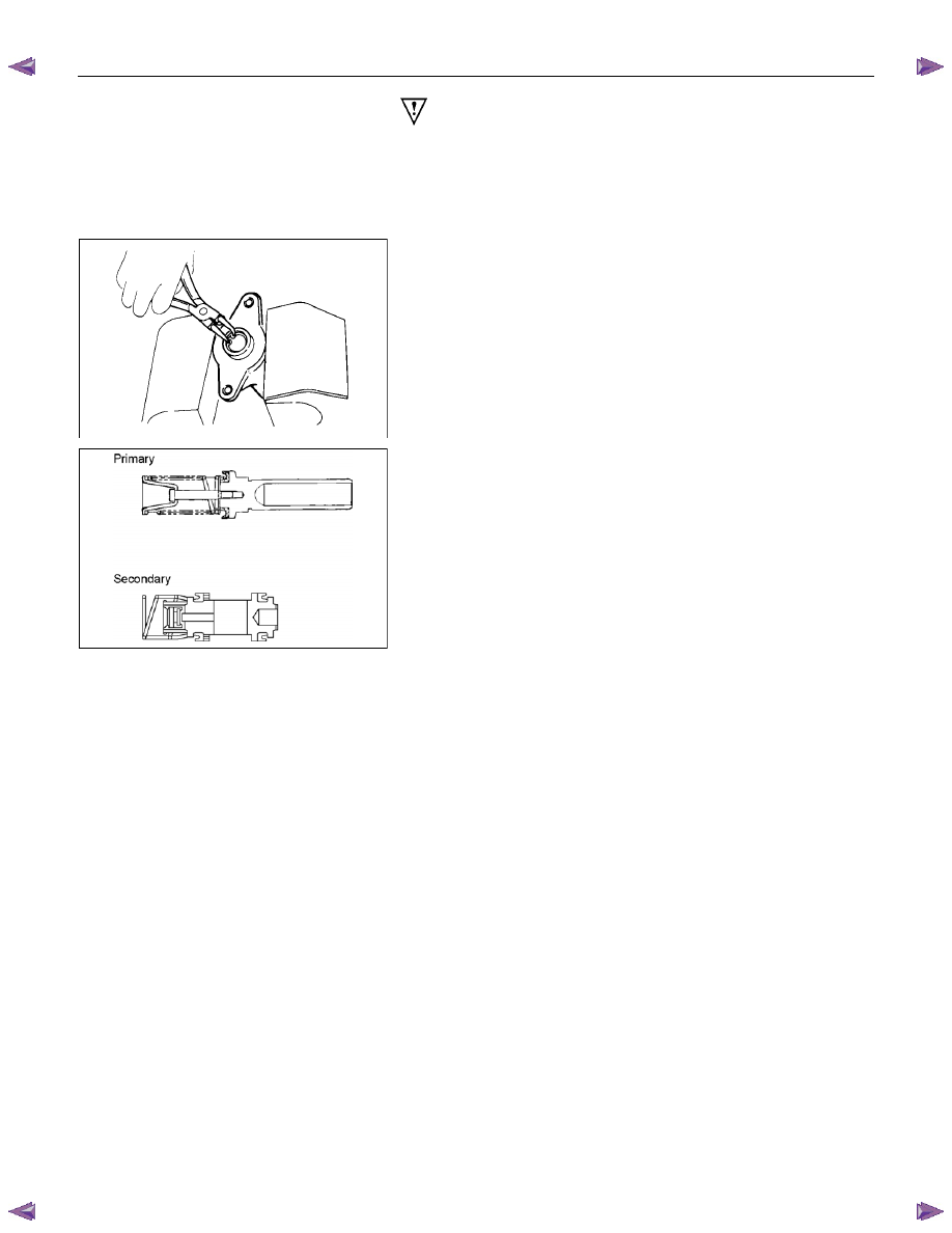
7. Front Seal
Front seal remain in the vacuum booster side, when removing
master cylinder.
9. Snap Ring
Remove the snap ring from the cylinder body with pushing in
the primary and secondary pistons.
10. Stopper Bolt and Gasket
Remove the stopper bolt from the cylinder body with pushing in
the primary and secondary pistons.
RTW75CSH002201
11. Primary Piston
12. Secondary Piston
Don’t remove the spring from the piston.
5C-56 BRAKES
INSPECTION AND REPAIR
Make necessary correction or parts replacement if wear damage or any other abnormal conditions are found
through inspection.
• Cylinder body inside face
• Piston
• Piston cup
• Return port, Supply port
• Return spring
• Guide assembly (O-ring, Cup)
• Front seal
Visual Check
Inspect the following parts for wear, distortion, cuts, nicks,
corrosion, or other abnormal conditions.
RTW75CSH002401
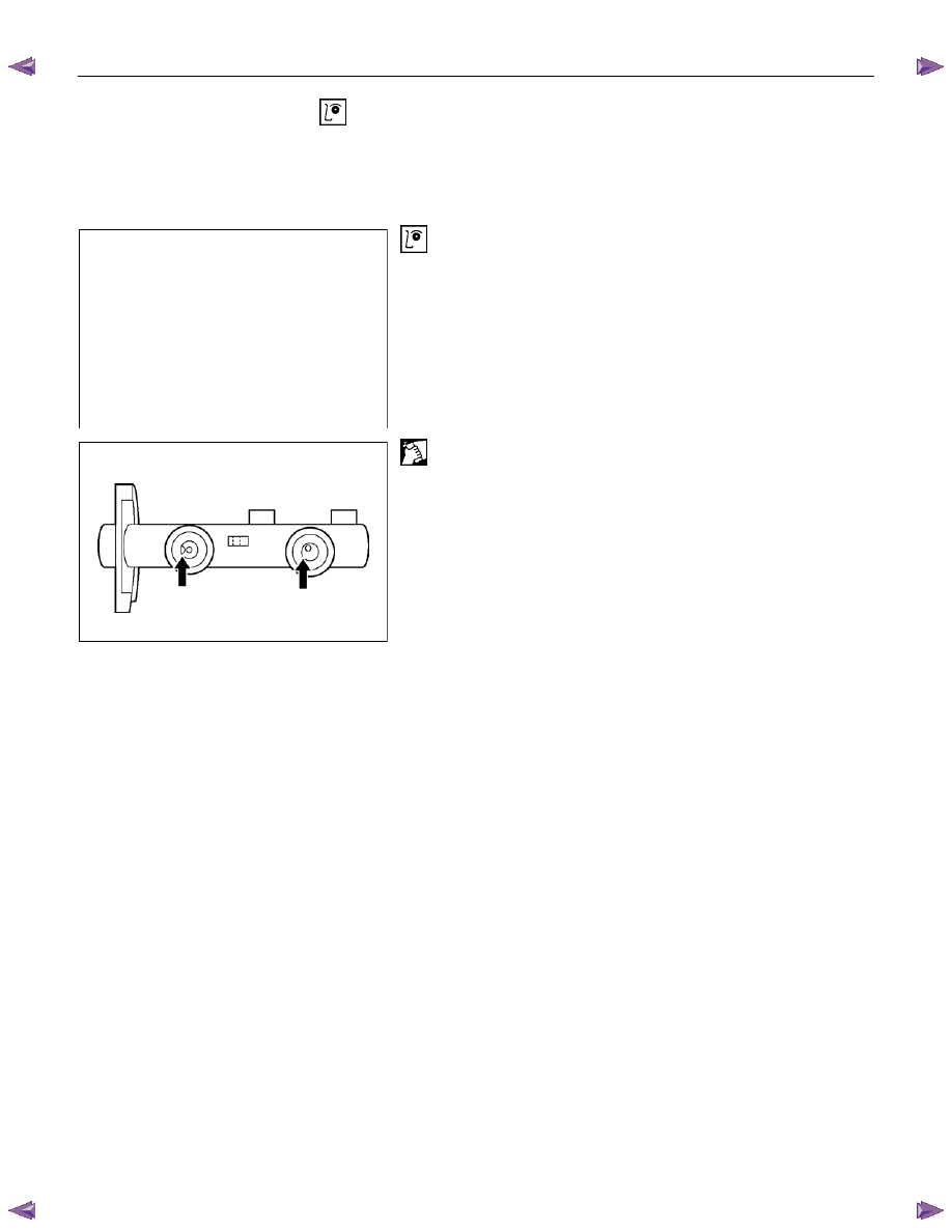
Return Port
Check the return port for obstructions and if necessary, clean
with a tag wire.
Blow away foreign matter with compressed air.
Нет комментариевНе стесняйтесь поделиться с нами вашим ценным мнением.
Текст