Isuzu KB P190. Manual — part 187
BRAKES 5C-49
Important Operations
Note:
• Wash the disassembled parts in clean brake fluid.
• Use compressed air to clean the ports.
• Protect the disassembled part surfaces from contamination
by dust and other foreign material.
• Before reassembly, check the part surfaces for
contamination with dust or other foreign material.
• Be sure to replace the designated parts with new ones.
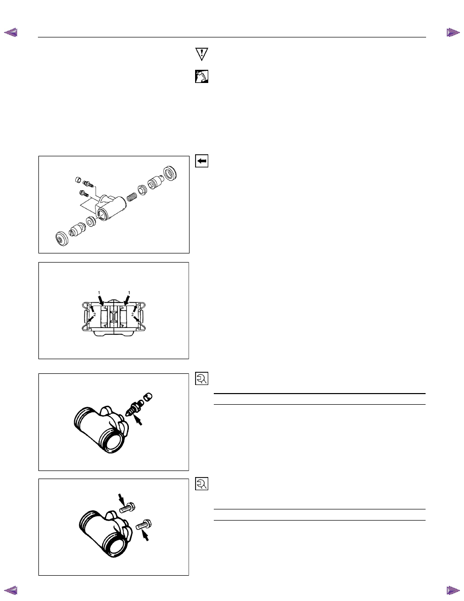
1. Piston Assembly
Install new piston cups on each piston so that the flared end of
the cups are turned to the inboard side of the pistons.
Attach the return spring and the boot to the piston.
Be sure to use new piston cup and boot.
RTW55CSH000201
• Apply brake fluid to the pistons and the inner face of the
boots.
• Note the direction of piston cup (1).
• Apply rubber grease to the boots (2) as shown in the
illustration.
5. Bleeder
Torque N
⋅m (kgf⋅m/Ib⋅in)
6 - 8 (0.6 – 0.8 / 52 - 69)
9. Wheel Cylinder Assembly
10. Bolt; Wheel cylinder
Torque N
⋅m (kgf⋅m/Ib⋅in)
14 - 18 (1.4 – 1.8 / 122 - 156)
5C-50 BRAKES
308R300008
11. Shoe; leading
• Be sure to use new spring; shoe hold.
12. Lever; parking
13. Washer; lever
14. Retainer
Install the lever, the washer and the retainer to the leading
brake shoe.
• Apply grease to the sliding surfaces of the lever and
brake shoe.
• Be sure to use new retainer and washer.
305R300009
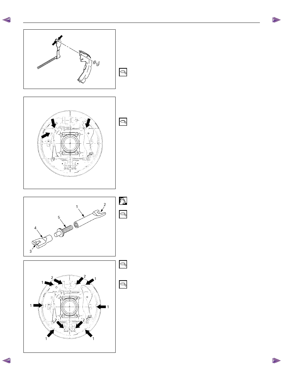
16. Shoe; trailing
• Be sure to use new spring; shoe hold.
17. Spring; shoe to shoe, upper
18. Adjuster assembly
1. Apply grease to each of the parts shown in the
illustration before installing the brake shoe.
• Lever; adjuster-shoe
• Adjuster-shoe
2. Clean the adjuster bolt (5) and the adjuster rods (1) (4).
Apply grease to the threaded portion of the adjuster bolt.
3. Install the adjuster rod to the adjuster bolt.
4. Apply grease to the adjuster arm ends (2) (3). Set the
spring upper to the adjuster arm, then install them to the
brake shoe.
305R300010
5. Before setting the brake shoes, apply grease to the back
plate portions (1) contacting the brake shoe edge as
shown in the illustration.
6. Apply grease to the wheel cylinder parts contacting the
brake shoe (2).
7. Install the brake shoe.
Note:
• Be careful not to damage the wheel cylinder dust cover.
• Do not allow the wheel cylinder piston to fly free.
BRAKES 5C-51
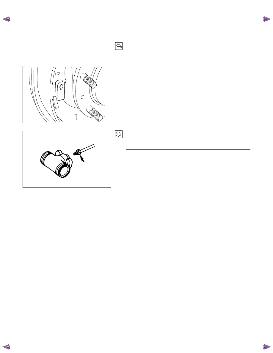
20. Lever; adjuster
21. Ring; Adjuster lever
• Apply grease to the lever adjuster sliding surface. Install
the lever adjuster and the ring to the shoe; trailing.
• Be sure to use a new ring.
RUW55CSH000501
22. Spring; shoe hold
23. Pin; shoe hold
• Install the brake drum.
• Install the rear wheel.
• If the wheel cylinder has been removed, the brake
system must be bled.
• Pump the brake pedal 10 times. Check that there is little
or no stroke length variation as the pedal is pumped.
• Adjust the lining clearance.
• Brake
Line
Torque N
⋅m (kgf⋅m/Ib⋅ft)
13 - 19 (1.3 - 1.9 / 9 - 14)
5C-52 BRAKES
BRAKE CONTROL
REMOVAL AND INSTALLATION
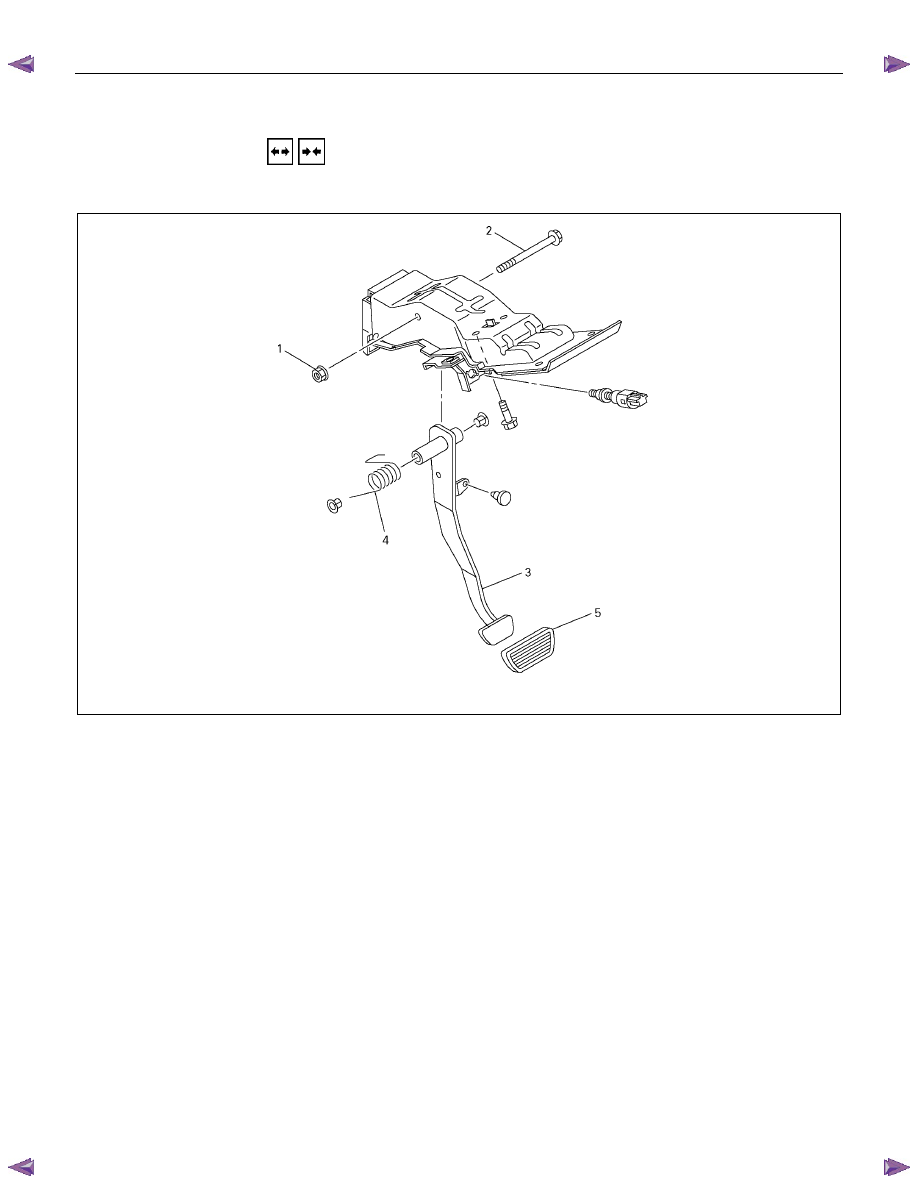
BRAKE PEDAL ASSEMBLY
This illustration is based on the RHD model
310R300001
Removal Steps
1. Nut; Fulcrum pin
2. Pin; Fulcrum, pedal to bracket
3. Pedal arm
4. Return spring
5. Pedal pad
Installation steps
To install, follow the removal procedure in
reverse order.
Before installation, apply grease to the entire
circumference of the fulcrum pin (2).
Refer to “SERVICING” in this section for
adjustment procedure of brake pedal.
Нет комментариевНе стесняйтесь поделиться с нами вашим ценным мнением.
Текст