Isuzu KB P190. Manual — part 189
BRAKES 5C-57
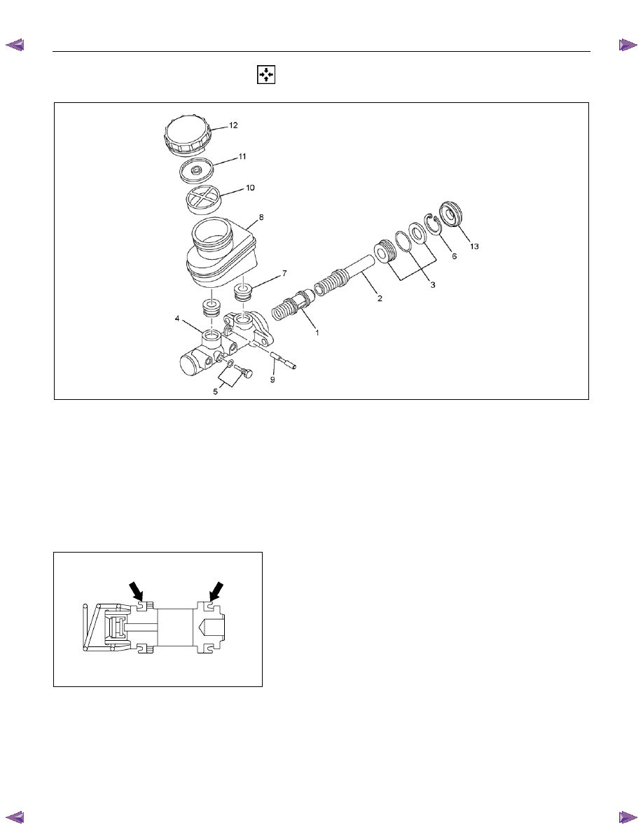
REASSEMBLY
RTW75CMF000801
Reassembly Steps
▲ 1. Secondary piston
▲ 2. Primary piston
▲ 3. Guide assembly
▲ 4. Cylinder body
▲ 5. Stopper bolt and gasket
▲ 6. Snap ring
▲ 7. Grommet
▲ 8. Reservoir tank
▲ 9. Pin
▲10. Filter
▲11. Diaphragm
▲12. Cap
▲13. Front seal
1. Secondary Piston
Lubricate the piston cups on the secondary piston assemblies
with brake fluid.
Note:
Be sure to use a new piston.

5C-58 BRAKES
RTW75CSH002301
2. Primary Piston
Lubricate the piston cup on the primary piston assemblies with
brake fluid (1).
Note:
Be sure to use a new piston.
3. Guide Assembly
Lubricate the O-ring of guide assembly with brake fluid (2) and
the cup of guide assembly with rubber grease (3) (0.2 ~ 0.3g).
RTW75CSH002001
4. Cylinder Body
Install the secondary piston and the primary piston to the
cylinder body.
Note:
The secondary piston long hole and the cylinder body stopper
bolt hole must be aligned at installation.
5. Stopper Bolt and Gasket
Install the stopper bolt to the cylinder body (the piston long hole
must be aligned with the cylinder body installation hole).
Tighten the bolts to the specified torque.
Torque N
⋅m (kgf⋅m/lb⋅in)
2 - 3 (0.2 - 0.3 / 17 - 26)
6. Snap Ring
Press down on the primary piston and install the snap ring to
the cylinder body groove.
Note:
Be sure to use new snap ring.
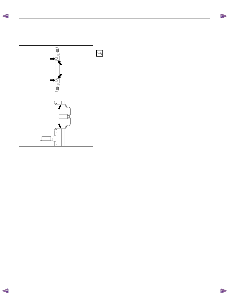
7. Grommet
1. Install the grommets to the reservoir tank.
Note:
Be sure to use are new grommets.
2. Install the reservoir tank to the cylinder body.
8. Reservoir Tank
9. Pin
BRAKES 5C-59
10. Filter
11. Diaphragm
12. Cap
RTW75CSH002501
13. Front Seal
1. Lubricate the front seal with silicon grease (0.3 ~ 0.5g).
RTW75CSH002601
2. Lubricate the front cylinder shell of vacuum booster with
silicon grease (0.2g).
5C-60 BRAKES
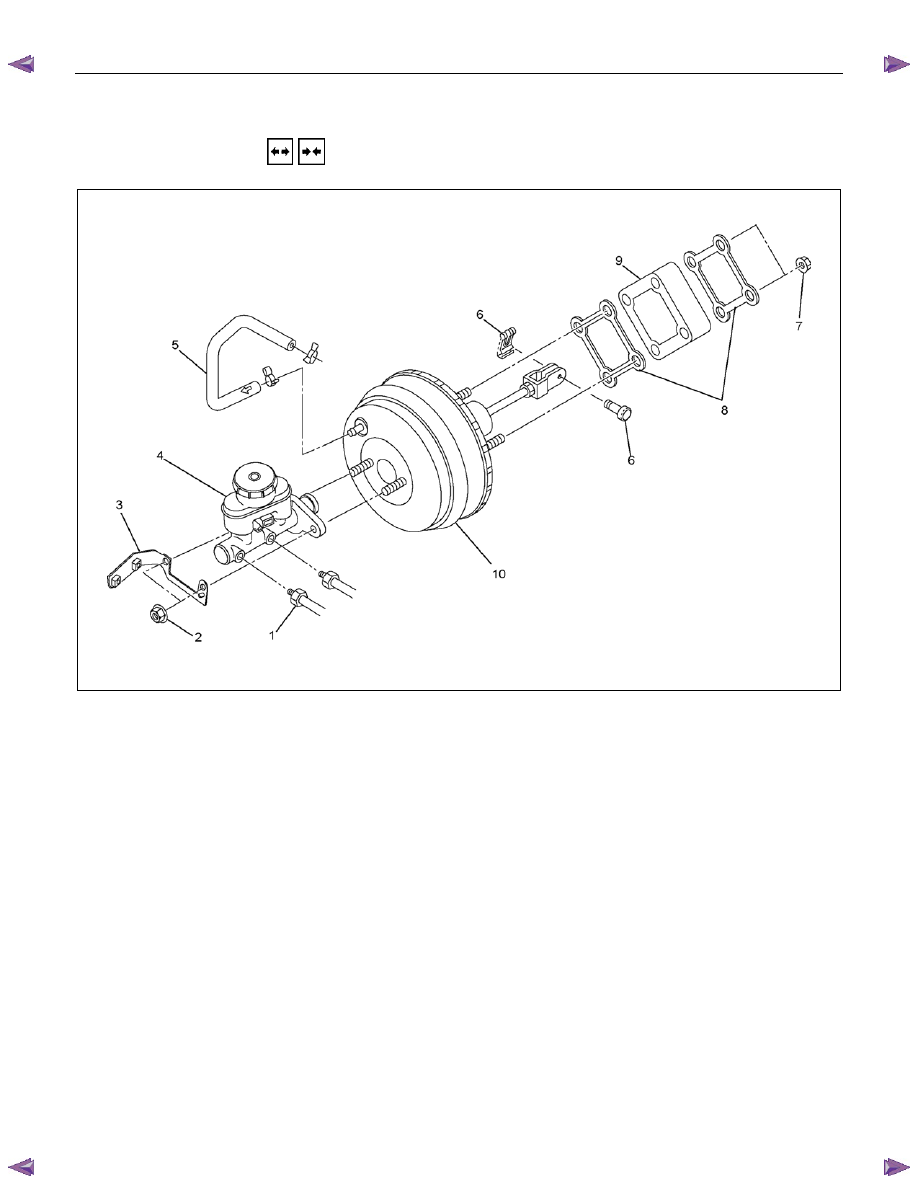
VACUUM BOOSTER
REMOVAL AND INSTALLATION
This illustration is based on the RHD model
RTW75CMF000501
Removal Steps
▲ 1. Brake pipe
▲ 2. Master cylinder fixing nut
▲ 3. Bracket
▲ 4. Master cylinder assembly
5. Vacuum hose
6. Snap pin
7. Vacuum booster fixing nut
8.
Gasket
9.
Spacer
10. Vacuum booster assembly
Installation Steps
▲10. Vacuum booster assembly
▲ 9. Spacer
▲ 8. Gasket
▲ 7. Vacuum booster fixing nut
▲ 6. Snap pin
▲ 5. Vacuum hose
4. Master cylinder assembly
3.
Bracket
2. Master cylinder fixing nut
1. Brake pipe
Нет комментариевНе стесняйтесь поделиться с нами вашим ценным мнением.
Текст