Isuzu KB P190. Manual — part 979
Automatic Transmission – 4L60E – On-vehicle Servicing
Page 7C4–3
1 General
Information
This Section describes the removal and reinstallation procedures of the four speed 4L60E hydra-matic automatic
transmission as well as the service operations which can be performed with the transmission still fitted to the vehicle.
1.1
General Service Information
Description
The shift selector mechanism is linked to the transmission manual shaft with a selector cable. A heat protector is fitted
over the neutral start and back-up switch and manual shaft select lever.
For rear wheel drive (RWD) vehicles an extension housing is fitted to the rear of the transmission case.
Four wheel drive (4WD) vehicles have an adaptor housing and transfer case fitted to the rear of the transmission case,
for description and service operation refer to 7D Transfer Case and Adaptor Housing.
The four speed 4L60E hydra-matic automatic transmission is fitted with a filler tube, a breather hose and a vent pipe for
hot fluid overflow.
The transmission fluid is driven through a cooler within the radiator via the cooler line/hose assemblies to maintain
normal operating temperature.
Service Information
Throughout the service operations within this
Section, when handling retaining clips, using
compressed air or cleaning fluids, wear safety
equipment to avoid personal injury.
Refer to 7C1 Automatic Transmission – 4L60E – General Information for the following:
•
information relating to mechanical and electrical operations,
•
abbreviations, transmission specifications, special tools and torque wrench specifications,
•
servicing, cleaning and inspection procedure recommendations.
It is essential to read and understand the General Information, Warnings, Cautions and Service Notes contained in that
same Section, before any service operation is performed on the four speed 4L60E hydra-matic automatic transmission or
any associated components.
Failure to comply with the procedures and service notes can affect the reliable and efficient operation of this automatic
transmission.
1.2
WARNINGS, CAUTIONS and NOTES
This Section contains various WARNINGS, CAUTIONS and NOTE statements that you must observe carefully to reduce
the risk of death or injury during service, repair procedures or vehicle operation. Incorrect service or repair procedures
may damage the vehicle or cause operational faults. WARNINGS, CAUTION and NOTE statements are not exhaustive.
GM HOLDEN LTD can not possibly warn of all the potentially hazardous consequences of failure to follow these
instructions.
Definition of WARNING, CAUTION and NOTE Statements
Diagnosis and repair procedures in this Section contain both general and specific WARNING, CAUTION and NOTE
statements. GM HOLDEN LTD is dedicated to the presentation of service information that helps the technician to
diagnose and repair the systems necessary for proper operation of the vehicle. Certain procedures may present a hazard
to the technician if they are not followed in the recommended manner. WARNING, CAUTION and NOTE statements are
designed to help prevent these hazards from occurring, but not all hazards can be foreseen.
Automatic Transmission – 4L60E – On-vehicle Servicing
Page 7C4–4
WARNING Defined
A WARNING statement immediately precedes an operating procedure or maintenance practice which, if not correctly
followed, could result in death or injury. A WARNING statement alerts you to take necessary action or not to take a
prohibited action. If a WARNING statement is ignored, the following consequences may occur:
•
Death or injury to the technician or other personnel working on the vehicle,
•
Death or injury to other people in or near the workplace area, and / or
•
Death or injury to the driver / or passenger(s) of the vehicle or other people, if the vehicle has been improperly
repaired.
CAUTION Defined
A CAUTION statement immediately precedes an operating procedure or maintenance practice which, if not correctly
followed, could result in damage to or destruction of equipment, or corruption of data. If a CAUTION statement is ignored,
the following consequences may occur:
•
Damage to the vehicle,
•
Unnecessary vehicle repairs or component replacement,
•
Faulty operation or performance of any system or component being repaired,
•
Damage to any system or components which depend on the proper operation of the system or component being
repaired,
•
Faulty operation or performance of any systems or components which depend on the proper operation or
performance of the system or component under repair,
•
Damage to fasteners, basic tools or special tools and / or
•
Leakage of coolant, lubricant or other vital fluids.
NOTE Defined
A NOTE statement immediately precedes or follows an operating procedure, maintenance practice or condition that
requires highlighting. A NOTE statement also emphasises necessary characteristics of a diagnostic or repair procedure.
A NOTE statement is designed to:
•
Clarify a procedure,
•
Present additional information for accomplishing a procedure,
•
Give insight into the reasons for performing a procedure in the recommended manner, and / or
•
Present information that gives the technician the benefit of past experience in accomplishing a procedure with
greater ease.
Automatic Transmission – 4L60E – On-vehicle Servicing
Page 7C4–5
2 Maintenance
Operations
2.1 Transmission
Fluid
When adding or changing the transmission fluid, use only the recommended automatic transmission fluid, refer to
0B Maintenance and Lubrication.
For the automatic transmission fluid diagnosis, refer to 7C3 Automatic Transmission – 4L60E – Hydraulic and
Mechanical Diagnosis.
Transmission Fluid Colour
New transmission fluid is red in colour due to a dye that is added to the fluid so it can be distinguished from other oils and
lubricants. The red dye is not permanent and as such, is not an indicator of the quality of the fluid.
As the vehicle is driven the transmission fluid will quickly look darker in colour and appear to be a light brown. A dark
brown colour with a distinctively burnt odour may indicate fluid deterioration and the need for fluid replacement.
N O T E
A dark brown fluid colour observed, coupled with
a reported delayed shift pattern may only indicate
that fluid replacement is required. This is not a
definite indication of a potential transmission
failure.
Transmission Fluid Level
N O T E
Carry out this operation with the transmission at
normal operating temperature (82 – 94°C), as the
temperature greatly affects the fluid level.
1
Drive the vehicle for a distance of at least 25 km to bring the transmission up to normal operating temperature.
If the transmission is not at normal operating
temperature and the correct procedure is not
followed, the result could be a false reading of
the fluid level on the transmission fluid
indicator.
2
If the vehicle has been operated under any of the following conditions, switch the engine off and allow the
transmission to cool for approximately thirty minutes:
•
in high ambient temperatures above 32° C,
•
at sustained high speeds,
•
in heavy stop / start city traffic during hot weather, or
•
towing.
3
Park the vehicle on level ground.
4
Move the gear selector to the Park position and apply the park brake.
5
Allow the engine to idle for 3 minutes with the accessories turned off.
Automatic Transmission – 4L60E – On-vehicle Servicing
Page 7C4–6
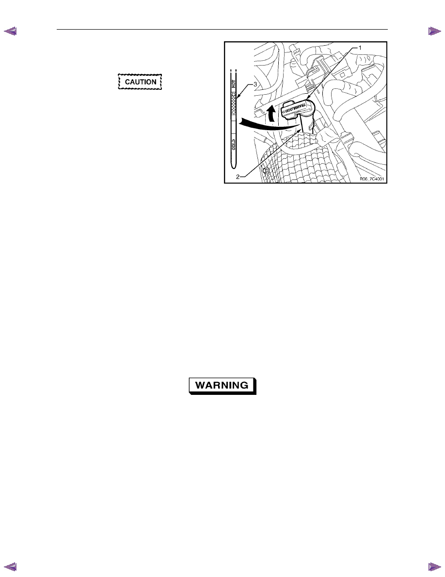
6
Lift the locking lever (1) on the transmission fluid
indicator, then remove the indicator from the filler
tube (2) and check the fluid colour, condition and level.
Do not overfill the transmission. Overfilling
can cause aeration resulting in fluid loss,
shift complaints and possible damage to the
transmission.
7
If the transmission fluid level is low, add only enough
of the recommended fluid until
its level shows onto the
crosshatch hot area (3) of the fluid indicator.
Figure 7C4 – 1
2.2
Reverse Flush and Flow Rate Test
It is essential to perform a reverse flush and oil cooler flow rate test after any of the following:
•
the transmission is repaired or replaced,
•
fluid contamination is suspected, or
•
whenever the oil pump and/or torque converter is replaced.
N O T E
The reverse flush must be completed prior to
conducting a flow rate test.
Reverse Flush
1
Disconnect both cooler hose/line assemblies at the transmission and at the radiator cooler, refer to
3.17
Transmission Cooler Line/Hose Assemblies.
2
Check the cooler hose/line to radiator cooler fittings for damage, replace as required.
To avoid personal injury, wear safety glasses
when using compressed air.
3
Carefully check the radiator cooler lower fitting to see if any foreign material is evident at this point. If foreign
material is found, remove it with a suitable tool and/or compressed air at a reduced pressure of approximately
345 kPa blown in the reverse direction through the cooler.
4
Using compressed air at a reduced pressure of approximately 345 kPa blown in a reverse direction, clean the
cooler hose/line assemblies.
5
Reconnect the cooler outlet line to the transmission and both cooler hose/line assemblies to the radiator cooler
fittings, refer to 3.17 Transmission Cooler Line/Hose Assemblies.
N O T E
Do not reconnect the cooler inlet line at the
transmission end. This line needs to be left
disconnected to perform the flow rate test.
6
Perform the flow rate test, refer to Flow Rate Test in this Section.
Нет комментариевНе стесняйтесь поделиться с нами вашим ценным мнением.
Текст