Isuzu KB P190. Manual — part 86

3C-24 FRONT SUSPENSION
Upper Ball Joint
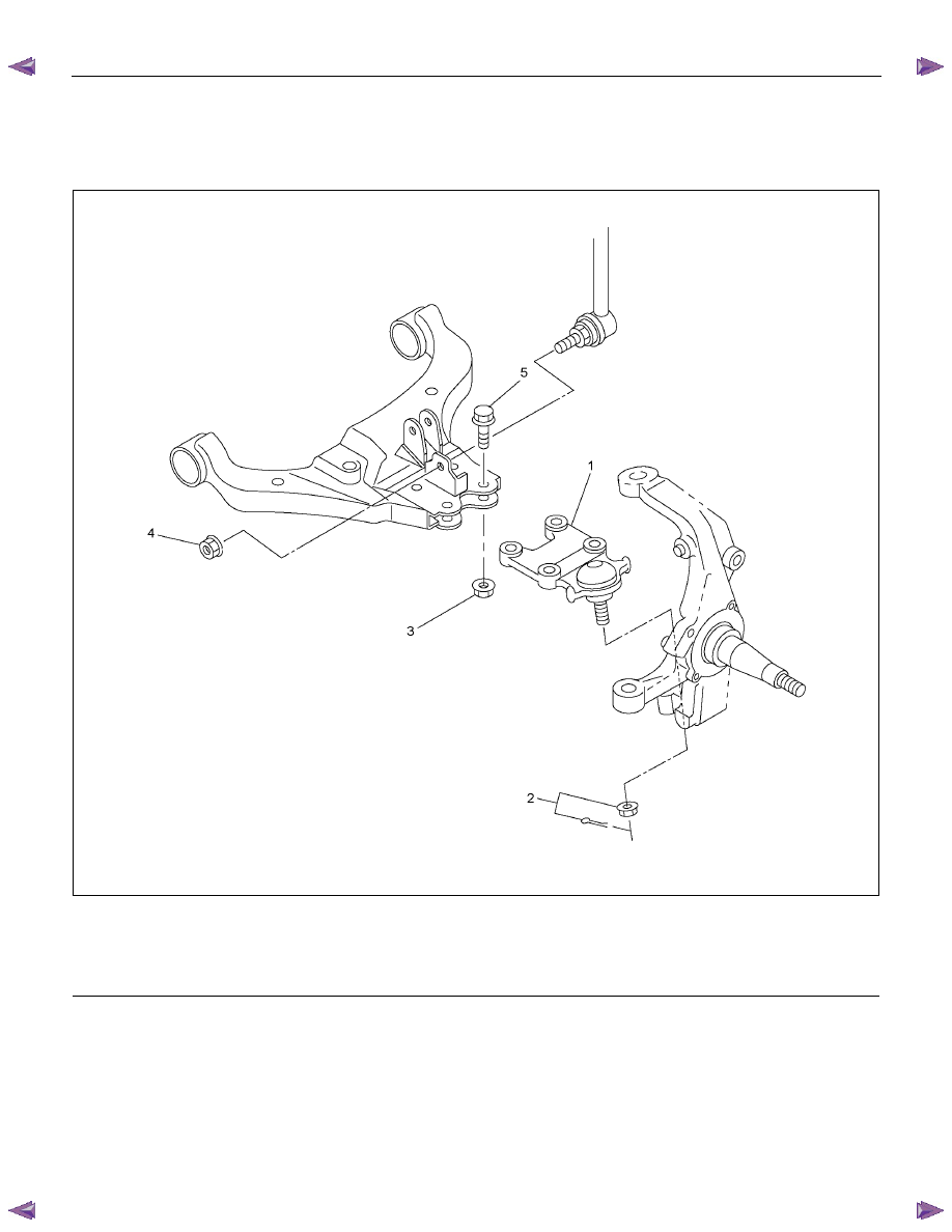
Upper Ball Joint and Associated Parts
RTW340LF001101
Legend
(1) Upper Ball Joint Bolt
(2) Upper Ball Joint
(3) Upper Ball Joint Nut
(4) Nut and Cotter Pin
(5) Link Nut
Removal
1. Raise the vehicle and support the frame with
suitable safety stands.
2. Remove wheel and tire assembly. Refer to wheel
in this section.
3. Remove link nut.
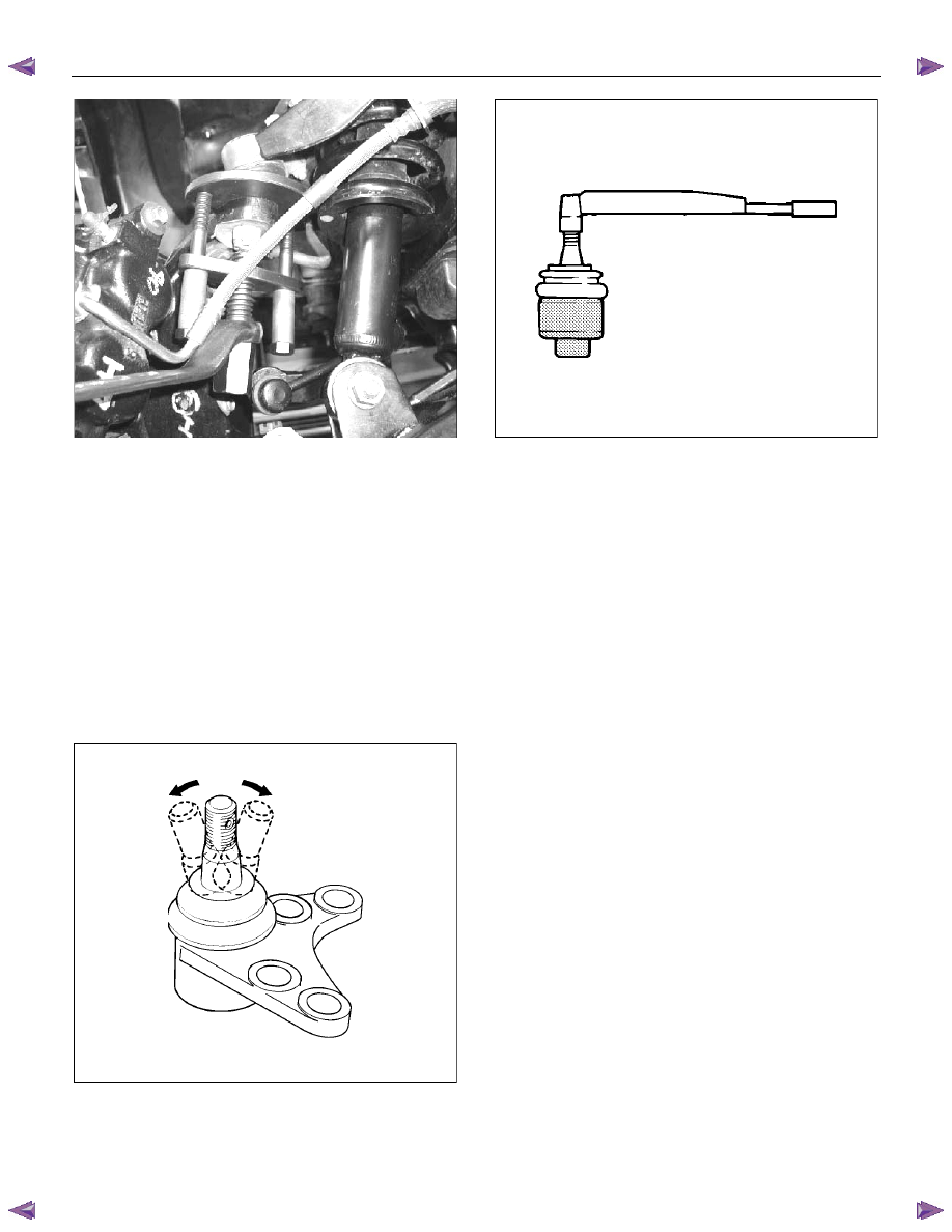
4. Remove upper ball joint nut and cotter pin, then
use remover 5-8840-2017-0 to remove the upper
ball joint from the knuckle.
CAUTION: Be careful not to damage the ball joint
boot and brake hose.
FRONT SUSPENSION 3C-25
P1010005
5. Remove upper ball joint bolt and nut.
6. Remove upper ball joint.
Inspection and Repair
Make necessary parts replacement if wear, damage,
corrosion or any other abnormal conditions are found
during inspection.
• Inspect the lower end of the boot for damage or
grease leaks. Move the ball joint as shown in the
figure to confirm its normal movement.
• Inspect screw/taper area of ball for damage.
• If any defects are found by the above inspections,
replace the ball joint assembly with new one.
450R300030
• After moving the ball joint 4 or 5 times, attach nut
then measure the preload.
Starting torque: 1.3-3.2 N
⋅⋅⋅⋅m (0.13-0.33 kgf⋅⋅⋅⋅m/0.9-
2.4 lb
⋅ft)
450RS024
If the above limits specified are exceeded, replace the
ball joint assembly.
Installation
1. Install upper ball joint.
2. Install upper ball joint bolt and nut, and then tighten
them to the specified torque.
Torque: 31 N
⋅⋅⋅⋅m (3.2 kgf⋅⋅⋅⋅m/23 lb⋅ft)
3. Install nut and cotter pin then tighten the nut to the
specified torque with just enough additional torque
to align cotter pin holes. Install new cotter pin.
Torque: 98 N
⋅⋅⋅⋅m (10.0 kgf⋅⋅⋅⋅m/72 lb⋅ft)
4. Install link nut, then tighten to the specified torque.
Torque: 50 N
⋅⋅⋅⋅m (5.1 kgf⋅⋅⋅⋅m/37 lb⋅ft)
3C-26 FRONT SUSPENSION
Lower Ball Joint
Lower Ball Joint and Associated Parts
RTW340LF002201
Legend
(1) Lower Ball Joint
(2) Nut and Cotter Pin
(3) Lower Ball Joint Nut
(4) Link Nut
(5) Lower Ball Joint Bolt
Removal
1. Raise the vehicle and support the frame with
suitable safety stands.
2. Remove wheel and tire assembly. Refer to Wheel
in this section.
3. Remove the link nut.
4. Support lower control arm with a jack.
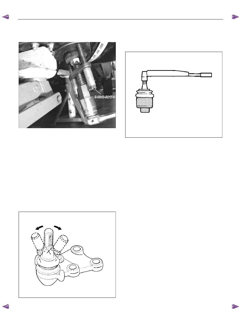
5. Remove lower ball joint nut and cotter pin, then
use remover 5-8840-2017-0 to remove the lower
ball joint from the knuckle.
FRONT SUSPENSION 3C-27
CAUTION: Be careful not to damage the ball joint
boot.
P1010003
6. Remove lower ball joint nut.
7. Remove lower ball joint bolt.
8. Remove lower ball joint.
Inspection and Repair
Make necessary parts replacement if wear, damage,
corrosion or any other abnormal condition is found
during inspection.
• Inspect the lower end of the boot for damage or
grease leaks. Move the ball joint as shown in the
figure to confirm its normal movement.
• Inspect screw/taper area of ball for damage.
• If any defects are found by the above inspections,
replace the ball joint assembly with new one.
450RS026
• After moving the ball joint 4 or 5 times, attach nut
then measure the preload.
Starting torque: 2.5-6.4 N
⋅⋅⋅⋅m (0.26-0.65 kgf⋅⋅⋅⋅m/1.9-
4.7 lb
⋅ft)
450RS024
• If the above limits specified are exceeded, replace
the ball joint assembly.
Installation
1. Install lower ball joint.
2. Install lower ball joint bolt.
3. Install lower ball joint nut and tighten it to the
specified torque.
Torque: 127 N
⋅⋅⋅⋅m (13.0 kgf⋅⋅⋅⋅m/94 lb⋅ft)
4. Install ball joint nut, then tighten it to the specified
torque with just enough additional torque to align
cotter pin holes. Install new cotter pin.
Torque: 147 N
⋅⋅⋅⋅m (15.0 kgf⋅⋅⋅⋅m/108 lb⋅ft)
5. Install link nut, then tighten to the specified torque.
Torque: 50 N
⋅⋅⋅⋅m (5.1 kgf⋅⋅⋅⋅m/37 lb⋅ft)
Нет комментариевНе стесняйтесь поделиться с нами вашим ценным мнением.
Текст