Isuzu KB P190. Manual — part 85
3C-20 FRONT SUSPENSION
Upper Control Arm
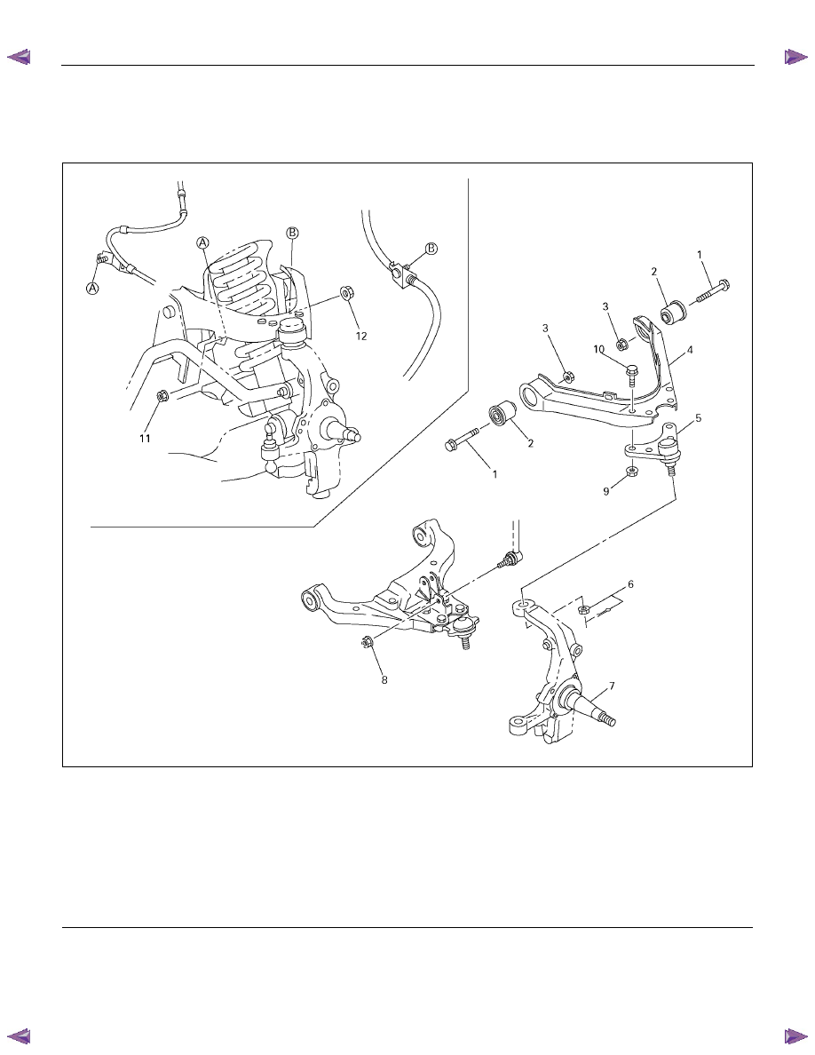
Upper Control Arm and Associated Parts
450R300038
Legend
(1) Upper Control Arm Bolt
(2) Bushing
(3) Upper Control Arm Nut
(4) Upper Control Arm Assembly
(5) Upper Ball Joint
(6) Nut and Cotter Pin
(7) Knuckle
(8) Link Nut
(9) Upper Ball Joint Nut
(10) Upper Ball Joint Bolt
(11) Speed Sensor Harness Nut
(12) Brake Fluid Hose Nut
Removal
1. Raise the vehicle and support the frame with
suitable safety stands.
2. Remove wheel and tire assembly. Refer to Wheel
in this section.
3. Remove speed sensor harness nut.
4. Remove brake fluid hose nut.
FRONT SUSPENSION 3C-21
5. Remove link nut.
6. Remove upper ball joint by using remover 5-8840-
2017-0.
CAUTION: Be careful not to damage the ball joint
boot.
P1010005
7. Remove upper control arm nut.
8. Remove upper control arm bolt.
9. Remove upper ball joint bolt and nut.
10. Remove upper ball joint.
11. Remove upper control arm assembly.
12. Remove bushing.
Inspection and Repair
Make necessary parts replacement if wear, damage,
corrosion or any other abnormal conditions are found
during inspection.
Check the following parts:
• Upper control arm
• Bushing
Installation
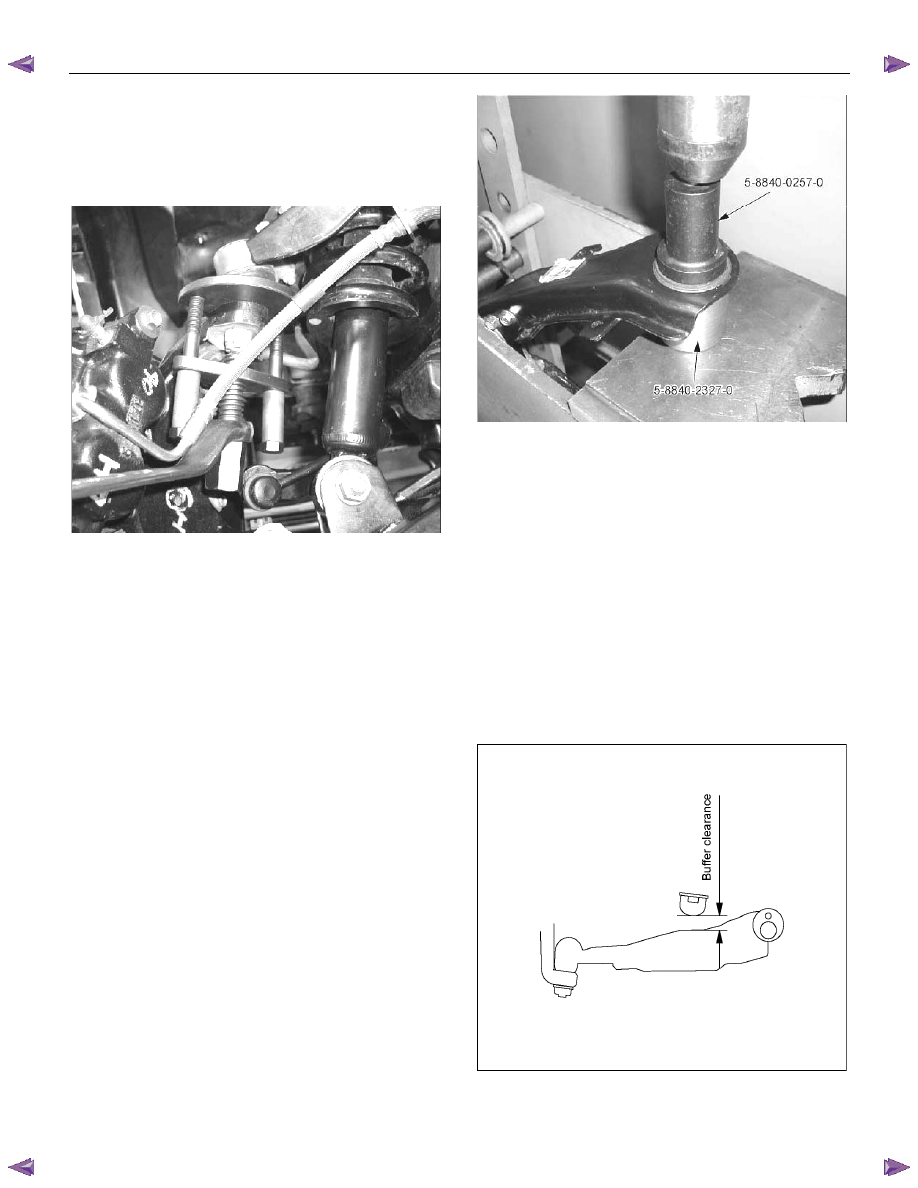
1. Install bushing by using installer 5-8840-0257-0
and 5-8840-2327-0.
P1010062
2. Install upper ball joint and tighten it to the specified
torque.
Torque: 31 N
⋅⋅⋅⋅m (3.2 kgf⋅⋅⋅⋅m/23 lb⋅ft)
3. Install nut and cotter pin then tighten the nut to the
specified torque, with just enough additional torque
to align cotter pin holes. Install new cotter pin.
Torque: 98 N
⋅⋅⋅⋅m (10.0 kgf⋅⋅⋅⋅m/72 lb⋅ft)
4. Install upper control arm assembly.
5. Install upper control arm bolt and nut.
NOTE: Apply oil to the thread.
NOTE: Tighten the bolt with the parts in the position
shown in the illustration below.
Buffer clearance: 25.9 mm (1.02 in)
Torque: 137 N
⋅⋅⋅⋅m (14.0 kgf⋅⋅⋅⋅m/101 lb⋅ft)
RTW53ASH000201
6. Install brake fluid hose nut.
7. Install speed sensor harness nut.

3C-22 FRONT SUSPENSION
Lower Control Arm
Lower Control Arm and Associated Parts
RTW340LF002301
Legend
(1) Cam bolt
(2) Bush
(3) Cam plate
(4) Lower Control Arm Nut
(5) Shock Absorber Nut
(6) Lower Ball Joint Bolt
(7) Lower Ball Joint
(8) Nut and cotter pin
(9) Lower Ball Joint Nut
(10) Link Nut
(11) Shock Absorber Bolt
Removal
1. Raise the vehicle and support the frame with
suitable safety stands.
2. Remove wheel and tire assembly. Refer to Wheel
in this section.
3. Remove the tie-rod end from the knuckle. Refer to
Power Steering Unit in Steering section.
FRONT SUSPENSION 3C-23
4. Support lower control arm with a jack.
5. Remove the link nut.
6. Remove the nut and cotter pin.
7. Remove the shock absorber lower end from the
lower control arm.
8. Remove the lower ball joint from the lower control
arm.
9. Remove lower control arm nut and cam plate.
10. Remove cam bolt.
11. Remove lower control arm.
12. Remove bushing.
Inspection and Repair
Make the necessary adjustments or parts replacement
if wear, damage, corrosion or any other abnormal
condition is found during inspection.
Check the following parts:
• Lower control arm
• Bushing
Installation
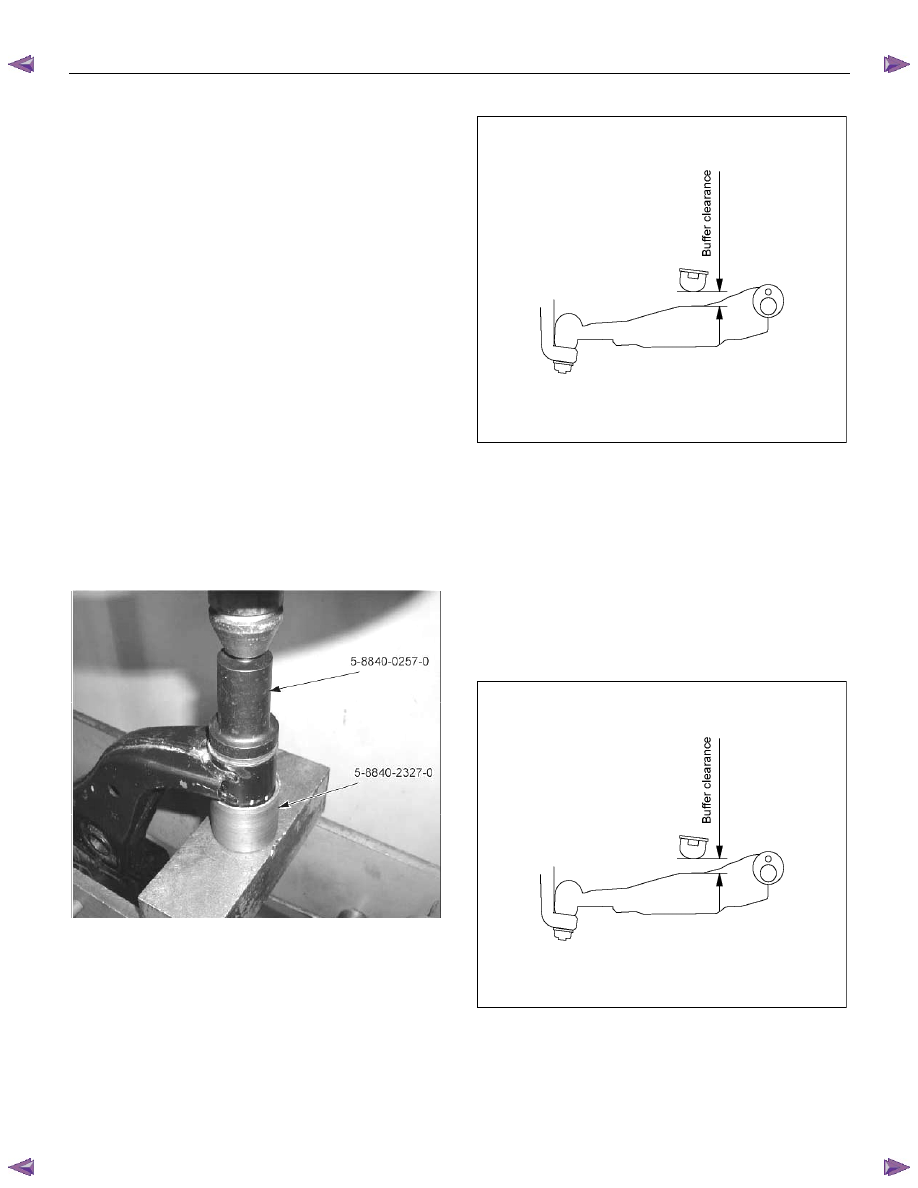
1. Install rear bushing by using installer 5-8840-
0257-0 and 5-8840-2327-0.
P1010063
2. Install lower control arm.
3. Install cam bolt.
4. Install lower ball joint and tighten it to the specified
torque.
Torque: 127 N
⋅⋅⋅⋅m (13.0 kgf⋅⋅⋅⋅m/94 lb⋅ft)
5. Install shock absorber and tighten it to the
specified torque.
NOTE: Apply oil to the thread.
NOTE: Tighten the lower control arm nut with the parts
in the position shown in the illustration below.
Torque: 137 N
⋅⋅⋅⋅m (14.0 kgf⋅⋅⋅⋅m/101 lb⋅ft)
RTW53ASH000201
6. Install stabilizer link and tighten it to the specified
torque.
Torque: 50 N
⋅⋅⋅⋅m (5.1 kgf⋅⋅⋅⋅m/37 lb⋅⋅⋅⋅ft)
7. Install lower control arm nut and cam plate and
tighten lower link nut finger-tight.
NOTE: Apply oil to the thread.
NOTE: Tighten the lower control arm nut with the parts
in the position shown in the illustration below.
Buffer clearance: 25.9 mm (1.02 in)
Torque: 186 N
⋅⋅⋅⋅m (19.0 kgf⋅⋅⋅⋅m/137 lb⋅⋅⋅⋅ft)
RTW53ASH000201
8. Install nut and cotter pin then tighten the nut to the
specified torque, with just enough additional torque
to align cotter pin holes. Install new cotter pin.
Torque: 147 N
⋅⋅⋅⋅m (15.0 kgf⋅⋅⋅⋅m/108 lb⋅ft)
Нет комментариевНе стесняйтесь поделиться с нами вашим ценным мнением.
Текст